liquid recirculation in microfluidic channels by the interplay of
advertisement
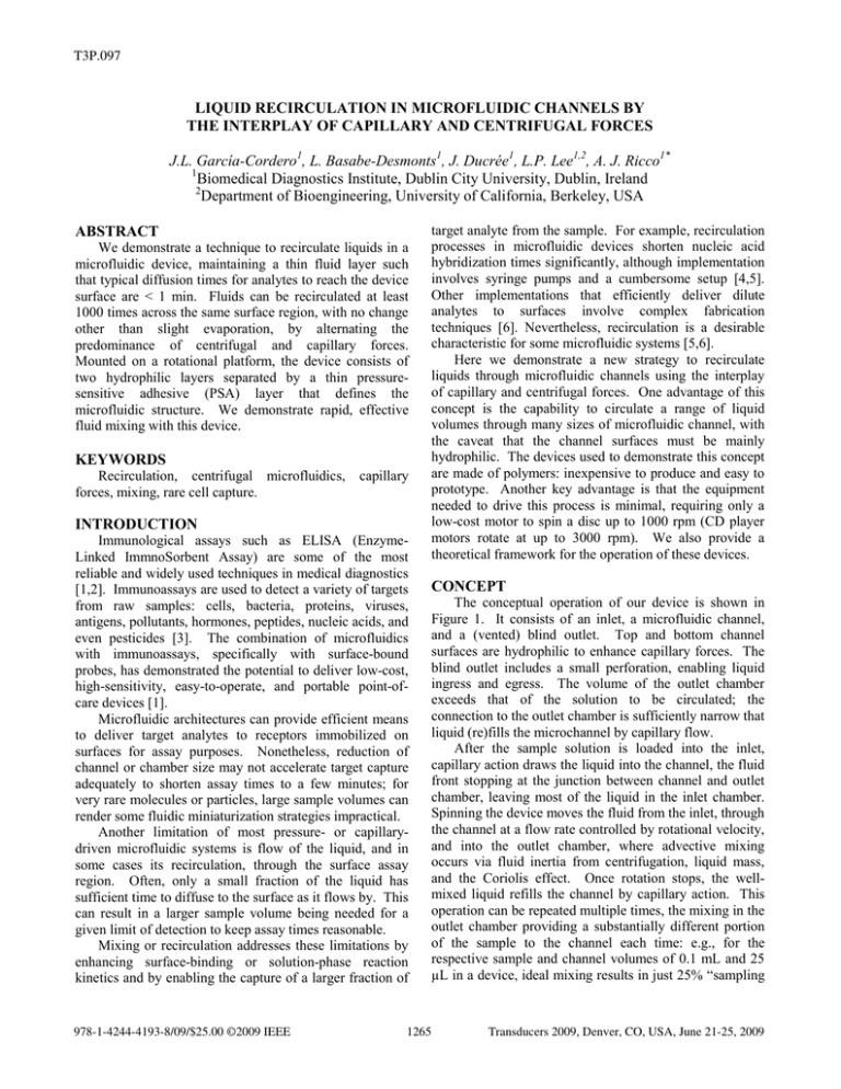
T3P.097 LIQUID RECIRCULATION IN MICROFLUIDIC CHANNELS BY THE INTERPLAY OF CAPILLARY AND CENTRIFUGAL FORCES J.L. García-Cordero1, L. Basabe-Desmonts1, J. Ducrée1, L.P. Lee1,2, A. J. Ricco1* 1 Biomedical Diagnostics Institute, Dublin City University, Dublin, Ireland 2 Department of Bioengineering, University of California, Berkeley, USA ABSTRACT We demonstrate a technique to recirculate liquids in a microfluidic device, maintaining a thin fluid layer such that typical diffusion times for analytes to reach the device surface are < 1 min. Fluids can be recirculated at least 1000 times across the same surface region, with no change other than slight evaporation, by alternating the predominance of centrifugal and capillary forces. Mounted on a rotational platform, the device consists of two hydrophilic layers separated by a thin pressuresensitive adhesive (PSA) layer that defines the microfluidic structure. We demonstrate rapid, effective fluid mixing with this device. KEYWORDS Recirculation, centrifugal microfluidics, forces, mixing, rare cell capture. capillary INTRODUCTION Immunological assays such as ELISA (EnzymeLinked ImmnoSorbent Assay) are some of the most reliable and widely used techniques in medical diagnostics [1,2]. Immunoassays are used to detect a variety of targets from raw samples: cells, bacteria, proteins, viruses, antigens, pollutants, hormones, peptides, nucleic acids, and even pesticides [3]. The combination of microfluidics with immunoassays, specifically with surface-bound probes, has demonstrated the potential to deliver low-cost, high-sensitivity, easy-to-operate, and portable point-ofcare devices [1]. Microfluidic architectures can provide efficient means to deliver target analytes to receptors immobilized on surfaces for assay purposes. Nonetheless, reduction of channel or chamber size may not accelerate target capture adequately to shorten assay times to a few minutes; for very rare molecules or particles, large sample volumes can render some fluidic miniaturization strategies impractical. Another limitation of most pressure- or capillarydriven microfluidic systems is flow of the liquid, and in some cases its recirculation, through the surface assay region. Often, only a small fraction of the liquid has sufficient time to diffuse to the surface as it flows by. This can result in a larger sample volume being needed for a given limit of detection to keep assay times reasonable. Mixing or recirculation addresses these limitations by enhancing surface-binding or solution-phase reaction kinetics and by enabling the capture of a larger fraction of 978-1-4244-4193-8/09/$25.00 ©2009 IEEE target analyte from the sample. For example, recirculation processes in microfluidic devices shorten nucleic acid hybridization times significantly, although implementation involves syringe pumps and a cumbersome setup [4,5]. Other implementations that efficiently deliver dilute analytes to surfaces involve complex fabrication techniques [6]. Nevertheless, recirculation is a desirable characteristic for some microfluidic systems [5,6]. Here we demonstrate a new strategy to recirculate liquids through microfluidic channels using the interplay of capillary and centrifugal forces. One advantage of this concept is the capability to circulate a range of liquid volumes through many sizes of microfluidic channel, with the caveat that the channel surfaces must be mainly hydrophilic. The devices used to demonstrate this concept are made of polymers: inexpensive to produce and easy to prototype. Another key advantage is that the equipment needed to drive this process is minimal, requiring only a low-cost motor to spin a disc up to 1000 rpm (CD player motors rotate at up to 3000 rpm). We also provide a theoretical framework for the operation of these devices. CONCEPT The conceptual operation of our device is shown in Figure 1. It consists of an inlet, a microfluidic channel, and a (vented) blind outlet. Top and bottom channel surfaces are hydrophilic to enhance capillary forces. The blind outlet includes a small perforation, enabling liquid ingress and egress. The volume of the outlet chamber exceeds that of the solution to be circulated; the connection to the outlet chamber is sufficiently narrow that liquid (re)fills the microchannel by capillary flow. After the sample solution is loaded into the inlet, capillary action draws the liquid into the channel, the fluid front stopping at the junction between channel and outlet chamber, leaving most of the liquid in the inlet chamber. Spinning the device moves the fluid from the inlet, through the channel at a flow rate controlled by rotational velocity, and into the outlet chamber, where advective mixing occurs via fluid inertia from centrifugation, liquid mass, and the Coriolis effect. Once rotation stops, the wellmixed liquid refills the channel by capillary action. This operation can be repeated multiple times, the mixing in the outlet chamber providing a substantially different portion of the sample to the channel each time: e.g., for the respective sample and channel volumes of 0.1 mL and 25 µL in a device, ideal mixing results in just 25% “sampling 1265 Transducers 2009, Denver, CO, USA, June 21-25, 2009 overlap” between two successive spin cycles; thus, a total of 16 cycles samples more than 99% of the fluid volume. compact disc (CD). Discs were subsequently mounted on the spindle of a brushless DC motor with an integrated optical encoder (Series 4490, Faulhaber, Switzerland). Flow of liquids was monitored using a high-sensitivity camera (Sensicam QE, PCO AG, Germany). Motor and camera were controlled by a host computer. The motor triggered the camera every revolution to acquire images of the spinning disc. Figure 1. Diagram of the process to recirculate liquids and capture scarce analytes. (A) Device schematic. Solution is loaded into the device (B), capillary forces draw liquid into the channel (C) until it reaches the outlet chamber, where it stops (D). Rotating the device displaces the liquid into the outlet (E). Immediately after stopping the device (F), liquid flows in the opposite direction (G) refilling the channel (H). This process is repeated to sample the entire fluid volume EXPERIMENTAL SECTION Fabrication Devices were fabricated using multi-layer lamination. A CO2 laser system (Laser Micromachining LightDeck, Optec, Belgium) was used to cut the various plastic layers. A thermal roller laminator (Titan-110, GBC Films, USA) was employed to laminate the polymer layers. For the assembly of all devices, the temperature in the laminator was set at 60 °C (pressure setting: 1.5 mm). Poly(methylmethacrylate) sheets (GoodFellow, UK) of different thickness were used as support layers. Microfluidic channels were cut from an 80-μm thick layer of double-sided PSA film (AR9808, Adhesives Research, Ireland). Top and bottom channel surfaces are hydrophilic (MH90368, Adhesive Research, Ireland) to enhance capillary forces. Final device assembly is shown in Figure 2. Figure 2. Assembly of the microfluidic device. The structure consists of 8 plastic layers assembled as shown above. PMMA is poly(methylmethacrylate); d-PSA is double-side pressuresensitive adhesive. The rectangular feature at right in the 5th – 8th layers from the bottom is the blind outlet chamber, the vent for which is a pinhole in the top layer. RESULTS AND DISCUSSIONS To characterize the circulation of liquids in channels using this technique, the two principal forces acting on the fluid at any given time must be accounted for. The capillary force acts in the opposite direction to the centrifugal force. The effect of the gravitational force is negligible so it is not be considered in these calculations. Capillary Pumping The interfacial pressure PC of the liquid front advancing into a rectangular channel is given by [3,7]: Characterization Fabricated devices were attached to a transparent 1266 ⎛ cos θ B + cos θT cos θ L + cos θ R ⎞ PC = −γ ⎜ + ⎟ d w ⎝ ⎠ (1) where γ is the surface tension of the liquid, d and w are the depth and width of the channel, respectively, and cosθB,T,L,R are the contact angles of the liquid with the surface of the bottom, top, left, and right walls, respectively. All contact angles ideally should be less than 90° – meaning surfaces should be hydrophilic – to enhance capillary (re)filling of the microfluidic channels. Centrifugal Pumping The apparent hydrostatic pressure created by the centripetal force at the start of the liquid plug is [8-10]: Pm = ρω 2 r Δr (2) where ρ is the density of the liquid and ω is the angular velocity of the disc. r is the average distance of the liquid plug in the channel from the center of rotation whereas Δr is the radial length of the liquid plug as shown in Figure 3. Δr and r are defined as: r= (ro + ri ) 2 Δr = ro − ri ( 2 PC = ρω 2 ro − ri 2 ri = ro − PC ρω 2 2 ) (5) (6) To verify this relationship, we fabricated three identical devices as described in the Experimental section, similar in design to the device shown in Figure 5. The depth, width, and length of the channel in these devices were 80 μm, 4 mm, and 3.5 cm, respectively, with an outer radius, ro, of 5.5 cm and initial inner radius, ri, of 2.0 cm. Contact angles of the top and bottom surfaces for deionized water were measured to be 12°, whereas those of the left and right walls were 110°. Surface tension for water is 72 dyn/cm and its density is 997 kg/m3. Substituting these values into Eq. 2 yields a capillary pressure of 560 Pa. Using this value in Eq. 6 allows calculation of the change in inner radius of the liquid plug as the speed of rotation increases, as shown in Figure 4. (3) (4) where ro and ri are the inner and outer radii of he liquid plug, respectively. Figure 4. Comparison of experimental and theoretical values obtained from Eq. 6 for fluid radial displacement, ri, versus the angular speed of the disc. Figure 3. Schematic diagram of the forces acting on the microfluidic channel during rotation of the disc. The centrifugal pressure counterbalances the capillary pressure, the two pushing the liquid in the opposite directions. ro remains constant at all times because the liquid cannot go further than this point. Also, the capillary pressure is constant at the front end of the liquid plug. The maximum speed of rotation needed to displace the liquid from the inlet to the outer edge of the microfluidic channel is easily calculated, as is the minimum speed needed for the liquid to return into the channel. The only condition that has to be met is that Pm is equal to PC; meeting this condition leads to the following formula: 1267 The results shown in Figure 4 suggest that the liquid plug starts moving in the outer radial direction just below 200 rpm, where the centrifugal pressure overcomes the capillary pressure. As the angular speed increases, the liquid plug advances until it reaches the end of the channel at 600 rpm. The time required to displace the full liquid plug to the blind outlet depends on the angular acceleration of the motor, which in this particular case can be as high as 4 rpm/ms between 200 and 600 rpm. Applications We fabricated two distinct devices to demonstrate the functionality and versatility of this novel concept. In one experiment, the device was spun 1000 times at 700 rpm for 5 sec each time, with a 5-sec pause between successive spin cycles to allow the channel to refill by capillary action. Figure 5 shows this device after 1000 recirculation cycles over 2.5 hr, at the end of which the channel continues to spontaneously refill. provided a theoretical framework with which to calculate the speeds of rotation needed to circulate the liquid, facilitating the design of new devices based on this technique. This new tool will increase analyte capture efficiency and consequently improve the speed and/or limits of detection of biosensors and bioassa ACKNOWLEDGMENTS This work was supported by Science Foundation Ireland under Grant No. 05/CE3/B754. REFERENCES Figure 5. Fabricated microfluidic channel, which contains 25 μL; the outlet chamber contains up to 100 µL. Part a shows in detail the inlet, blind outlet, and vent. After loading the solution into the inlet chamber, several bubbles form (blue arrows). Part b shows the same device after 1000 recirculation cycles over 2.5 hr. Notice that the liquid initially visible in the inlet hole has been fully transferred to the blind outlet chamber; also note that there are no more bubbles in the channels. Scale bar: 5 mm. Figure 6 shows that two liquids are mixed effectively using the same principle: 3 cycles over a total of 30 sec resulted in complete mixing, as shown in the photograph. Figure 6. Complete mixing of two liquids. Part a shows two microfluidic channels, the left one filled with 3 μL of red dye and the right one with water. After recirculating by rotation and pausing for refill three times (30 sec total elapsed time), the solution is completely mixed, as shown in b. Scale bar: 5 mm. CONCLUSIONS We have demonstrated a new technique to recirculate large-volume samples in microfluidic channels using a rotational platform. The interplay of capillary and centripetal forces makes it possible to move the liquid through the channel multiple times, bringing each time a freshly mixed sample into the channel. We have also 1268 [1] S. Sia, V. Linder, B. Parviz, A. Siegel, G. Whitesides, “An Integrated Approach to a Portable and Low-Cost Immunoassay for Resource Poor Settings”, Angew. Chem. Int. Ed., vol. 43, pp. 498-502, 2004. [2] T. Squires, R. Messinger, S.Manalis, “Making it stick: convection, reaction and diffusion in surface-based biosensors”, Nat. Biotech., vol. 26, pp. 417-426, 2008. [3] E. Delamarche, D. Juncker, H. Schmid, “Microfluidics for processing surfaces and miniaturizing biological assays”, Adv. Mater., vol. 17, pp. 2911-2933, 2005. [4] H. H. Lee, J. Smoot, Z. McMurray, D. Stahl, P. Yager, “Recirculating flow accelerates DNA microarray hybridization in a microfluidic device”, Lab Chip, vol. 6, pp. 1163-1270, 2006. [5] P. K. Yuen, G. Li, Y. Bao, U. Müller, “Microfluidic devices for fluidic circulation and mixing improve hybridization signal intensity on DNA arrays”, Lab Chip, vol. 3, pp. 46-50, 2003. [6] R. Lammertink, S. Schlautmann, G. Besselink, R. Schasfoort, “Three-dimensional microfluidic confinement for efficient sample delivery to biosensor surfaces. Application to immunoassays on planar optical waveguides”, Anal. Chem., vol. 74, pp. 52435250, 2002. [7] D. Juncker, H. Schmid, U. Drechsler, H. Wolf, B. Michel, N. Rooij, E. Delamarche, “Autonomous microfluidic capillary system”, Anal. Chem., vol. 74, pp. 6139-6144, 2002. [8] D. Duffy, H. Gillis, J. Lin, N. Sheppard, G. Kellogg, “Microfluidic centrifugal microfluidic systems: characterization and multiple enzymatic assays”, Anal. Chem., vol. 71, pp. 4669-4678, 1999. [9] M. Madou, J. Zoval, G. Jia, H. Kido, J. Kim, N. Kim, “Lab on a CD”, Ann. Rev. Biomed. Eng., vol. 8, pp. 601-628, 2006. [10] M. Liu, J. Zhang, Y. Liu, W. Lau, J. Yang, “Modeling of flow burst, flow timing in lab-on-a-CD systems and its application in digital chemical analysis”, Chem. Eng. Technol, vol. 31, pp. 13281335, 2008. CONTACT * A.J. Ricco, tel: +1-650-604-4276; ajricco@alum.mit.edu
