MET Tutorial
advertisement
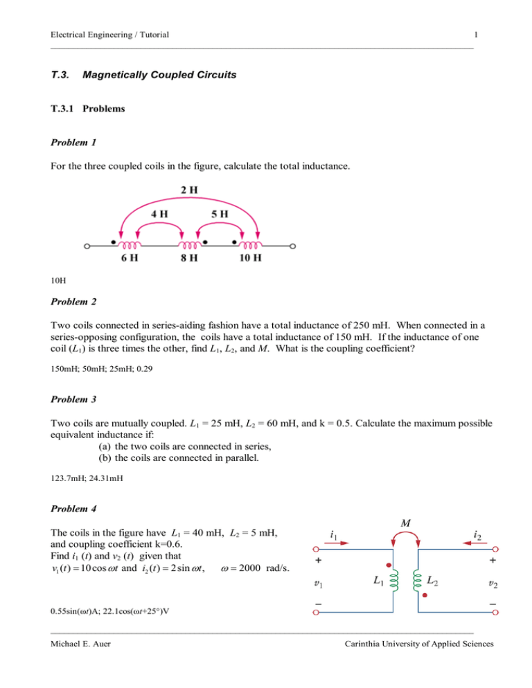
Electrical Engineering / Tutorial 1 ______________________________________________________________________________________________ T.3. Magnetically Coupled Circuits T.3.1 Problems Problem 1 For the three coupled coils in the figure, calculate the total inductance. 10H Problem 2 Two coils connected in series-aiding fashion have a total inductance of 250 mH. When connected in a series-opposing configuration, the coils have a total inductance of 150 mH. If the inductance of one coil (L1) is three times the other, find L1, L2, and M. What is the coupling coefficient? 150mH; 50mH; 25mH; 0.29 Problem 3 Two coils are mutually coupled. L1 = 25 mH, L2 = 60 mH, and k = 0.5. Calculate the maximum possible equivalent inductance if: (a) the two coils are connected in series, (b) the coils are connected in parallel. 123.7mH; 24.31mH Problem 4 The coils in the figure have L1 = 40 mH, L2 = 5 mH, and coupling coefficient k=0.6. Find i1 (t) and v2 (t) given that = v1 (t ) 10 cos= ωt and i2 (t ) 2sin = ωt , ω 2000 rad/s. 0.55sin(ωt)A; 22.1cos(ωt+25°)V ______________________________________________________________________________________________ Michael E. Auer Carinthia University of Applied Sciences Electrical Engineering / Tutorial 2 ______________________________________________________________________________________________ Problem 5 Find v(t) for the circuit below. v(t) = 24.25cos(4t–14.03˚) V Problem 6 In the circuit, ZL is a 15-mH inductor having an impedance of j40 Ω. Determine Zin when k=0.6. 13.073 + j25.86 Ω Problem 7 A 4800-V rms transmission line feeds a distribution transformer with 1200 turns on the primary and 28 turns on the secondary. When a 10-Ω load is connected across the secondary, find: (a) the secondary voltage, (b) the primary and secondary currents, (c) the power supplied to the load. 112V; 261mA; 11.2mA; 1254W ______________________________________________________________________________________________ Michael E. Auer Carinthia University of Applied Sciences


