Clear Pulse Co. Ltd.
advertisement

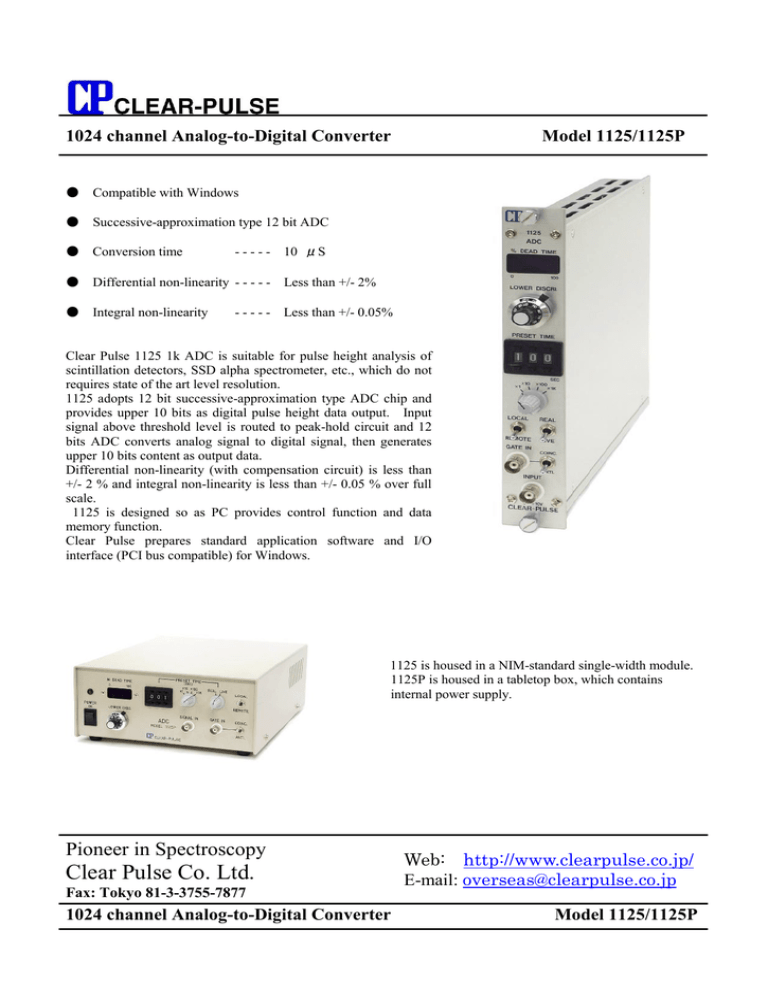
1024 channel Analog-to-Digital Converter Model 1125/1125P ● Compatible with Windows ● Successive-approximation type 12 bit ADC ● Conversion time - - - - - 10 μS ● Differential non-linearity - - - - - Less than +/- 2% ● Integral non-linearity - - - - - Less than +/- 0.05% Clear Pulse 1125 1k ADC is suitable for pulse height analysis of scintillation detectors, SSD alpha spectrometer, etc., which do not requires state of the art level resolution. 1125 adopts 12 bit successive-approximation type ADC chip and provides upper 10 bits as digital pulse height data output. Input signal above threshold level is routed to peak-hold circuit and 12 bits ADC converts analog signal to digital signal, then generates upper 10 bits content as output data. Differential non-linearity (with compensation circuit) is less than +/- 2 % and integral non-linearity is less than +/- 0.05 % over full scale. 1125 is designed so as PC provides control function and data memory function. Clear Pulse prepares standard application software and I/O interface (PCI bus compatible) for Windows. 1125 is housed in a NIM-standard single-width module. 1125P is housed in a tabletop box, which contains internal power supply. Pioneer in Spectroscopy Clear Pulse Co. Ltd. Fax: Tokyo 81-3-3755-7877 1024 channel Analog-to-Digital Converter Web: http://www.clearpulse.co.jp/ E-mail: overseas@clearpulse.co.jp Model 1125/1125P Major Specifications Input Input Signal Rise Time Pulse Width Input Impedance Connector Lower Level Discriminator Upper Level Discriminator Gate Signal Gate Signal Mode Analog to Digital Converter Resolution Conversion Time Differential Non-linearity Integral Non-linearity Timer Local Multiplier Remote Local/ Remote Data Output Output Signal Output Resolution Output impedance Control Signal Input Input level Input impedance Control Signal Output Control Signal Output Output level Output impedance Dead Time Display Power Required 1125 1125P Dimensions 1125 1125P 0 to +10 V, unipolar, or bipolar Gaussian-shaped signal 0.5μS minimum 0.5 to 10μS 1 kΩ BNC 0 to +5 V by front panel 10-turn potentiometer +9 to +10 V TTL POS level; Input Impedance: 2 kΩ Coincidence, Anti-Coincidence, and Trigger by front panel toggle switch 12 bits/ 10 V 10μS Less than +/- 2 % Less than +/- 0.05 % (5 % to 95 % range) 1 to 999 sec x1, x10, x100, x1k by digital or mechanical switch Real-time/ Live-time selectable by front panel switch By connected PC By front panel toggle switch TTL neg level 13 bits (8192 channel) Can be set to 8192, 4096, 2048, or 1024 ch by software Corresponding to 74LS374 TTL neg level: Reset, Data-read, Wait, Output-enable 330 Ω TTL neg level: Data-ready, Stop, Switch stop, Time over Corresponding to 74LS374 LED bar-graph display (%) +24 V: -24 V: +6 V: -6V AC 100V, 50/60 Hz NIM-standard single-width module 210 (W) x 99 (H) x 270 (D) mm Interface and standard application program 1114A-1 Standard application software compatible with Windows Parallel I/O board (Compatible with PCI bus) Pioneer in Spectroscopy Clear Pulse Co. Ltd. Fax: Tokyo 81-3-3755-7877 Web: http://www.clearpulse.co.jp/ E-mail: overseas@clearpulse.co.jp


