NCEA Collated questions
advertisement
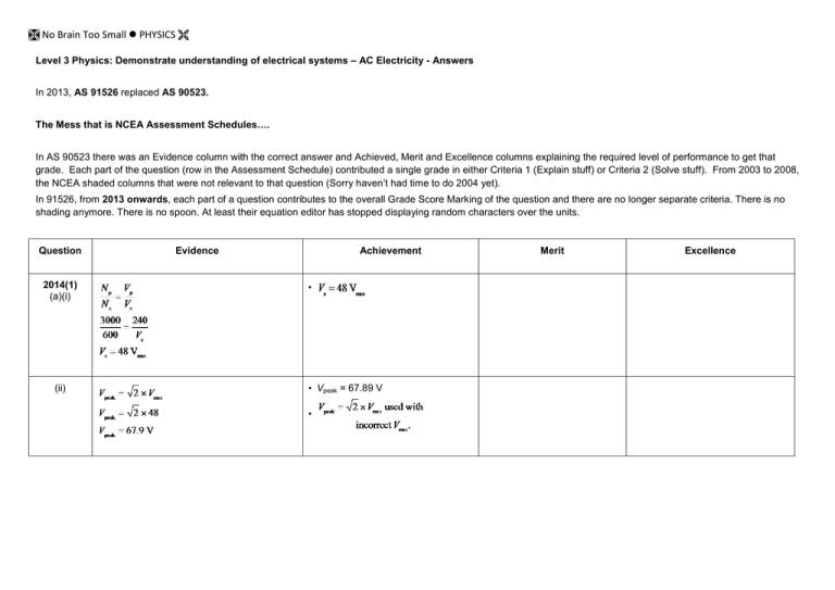
No Brain Too Small PHYSICS Level 3 Physics: Demonstrate understanding of electrical systems – AC Electricity - Answers In 2013, AS 91526 replaced AS 90523. The Mess that is NCEA Assessment Schedules…. In AS 90523 there was an Evidence column with the correct answer and Achieved, Merit and Excellence columns explaining the required level of performance to get that grade. Each part of the question (row in the Assessment Schedule) contributed a single grade in either Criteria 1 (Explain stuff) or Criteria 2 (Solve stuff). From 2003 to 2008, the NCEA shaded columns that were not relevant to that question (Sorry haven’t had time to do 2004 yet). In 91526, from 2013 onwards, each part of a question contributes to the overall Grade Score Marking of the question and there are no longer separate criteria. There is no shading anymore. There is no spoon. At least their equation editor has stopped displaying random characters over the units. Question 2014(1) (a)(i) (ii) Evidence Achievement • • Vpeak = 67.89 V • Merit Excellence No Brain Too Small PHYSICS (b) (c) (d) 2013(3) (a) The rms voltage is the root mean squared voltage. The rms is a kind of average voltage used because the average of a sin function over time is zero. The rms voltage has the same magnitude as the DC voltage that would deliver the same power output as the AC voltage being described. • The rms is a kind of average voltage, used because the average voltage is zero because the voltage varies / sin wave. • The rms voltage has the same magnitude as the DC voltage that would deliver the same power output as the AC voltage being described. • Sketch showing AC voltage, average V and Vrms. • Peak values reached for a short time only because of sin curve / V increasing and decreasing (it is the average V is wrong). • XL= 5.2 Ω. • Correct method of calculating Z using incorrect reactance. • Correct phasor. • No phasor but correct explanation. • • • • XC = XL VC = VL Z=R Calculated f0 and then XC (XL correct in 1c). • Correct answer. • Correct phasor diagram drawn with correct explanation. • Z = 6.36 Ω. • • Calculated f0 and then XC (XL not calculated in 1c) • No Brain Too Small PHYSICS (b) The current is in phase with the resistance and the supply voltage is in phase with the impedance. • Recognition that voltage phase difference is the same as impedance phase difference. OR • θ is labelled correctly in the diagram • Correct answer. 54° or 0.89 rad • Correct Xtot. 75Ω OR • If the value of XL is substituted as 98.6 and then te Z is calculated as 93 Ω. Correct answer 99 Ω. • Recognition that the frequency has to be decreased to make the Xc = XL. OR • Recognition that the frequency has to be decreased, as by decreasing f, the XL decreases and XC increases. Achievement + • By decreasing f, the XL decreases and XC increases. 93 Ω θ 55 Ω Current lags the supply voltage by 54° or 0.94 rad. (c) (d) (e) To bring the circuit to resonance, the frequency must be changed to make the two reactances equal in value. XL is directly proportional to f and XC is inversely proportional to f so changing the frequency will increase one but decrease the other. XL > XC and so to decrease XL and increase XC, frequency must be decreased. • Correct answer. 0.0350H. No Brain Too Small PHYSICS (f) When the circuit is in resonance, the current is greatest because the reactance is zero and so the impedance is smallest. When the current is greatest the sound from the speaker is loudest. The current decreases rapidly either side of resonance because the reactance increases either side of resonance. So if the frequency is reduced quickly through the resonant frequency and down below it, there will be a brief surge of current and so a brief burst of sound. • Recognition that the max sound happens at resonance. OR • Recognition that the frequency must be changed down through the resonant frequency. OR • Current-frequency diagram. • Achievement. AND • Maximum current at resonance explained. 2012(3) (a) 2 (b) 2 Correct impedance. 176.4 Ω OR Incorrect impedance but consequentially correct calculation for current. 1 3 sf for the current value. 2 (c) 1 2 Correct working. Demonstrates knowledge that at resonance. 1 3 sf Correct current. 28.3mA Correct answer. • Full explanation linking greatest sound to maximum current and zero reactance / impedance = R at resonance Rapid decline in current either side of resonance requires bringing the frequency quickly through the resonant frequency. No Brain Too Small PHYSICS (d) The current caused by 49 MHz circuit is much smaller than the current caused by 27MHz. At 49 MHz, XL increases and Xc decreases, increasing the overall impedance, thus current decreases and the toy car does not respond due to smaller current. Circuit has greater impedance to 49 MHz. OR 49 MHz produces less current. At 49 MHz, XL increase and Xc decreases. (So the total impedance increases ) and the current decreases. 1 or 2 1 or 2 Finds current 106 mA at 27.0 MHz. Correct current 106mA and correct Z at 49 MHz, 219 Ω. OR Incorrect value for 106 mA, but correct value 22.8 mA. 2 Correct current values 106 mA and 22.8 mA. No Brain Too Small PHYSICS 2011(1) (d) • When the input voltage > Vc, the capacitor charges. • When the input voltage < Vc, the capacitor discharges. • Because it takes time to charge and discharge, the voltage across the capacitor remains more stable than the input. • Because Vc is proportional to Q. • This works if the time constant for the circuit is similar or larger than the time period of the signal. Links smoothing to charge / discharge of capacitor. 1 Explanation includes time taken for capacitor to charge / discharge. 1 Clear links between time constant, changing charge on the capacitor and output voltage. 2 2011(2) (a) (b) 1 Correct working and answer. Time period for the supply is 2.0 s. Correct calculation of ω,T, f or Xc. 2 2 1 2 2 Shows VL, VC VS phasors in the correct directions. (c) 10V 1V VL Vc θ Vsupply I 9V Correct calculation of ω and Xc. 2 Complete diagram showing enough correct detail for calculation of phase angle. Complete correct answer. Complete correct answer. No Brain Too Small PHYSICS (d) VL > VC resonance occurs when VL = VC (and XL = XC) 1 1 1 1 Demonstrates understanding of the condition for resonance. OR Demonstrates understanding of how capacitive and inductive reactance are related to frequency. Demonstrates understanding of the condition for resonance, AND Demonstrates understanding of how capacitive and inductive reactance are related to frequency. Thus the frequency should be reduced, decreasing XL and increasing XC 2011(2) (c) At resona nce X C = X L 1 =ωL ωC 1 = ω2 LC 2π f = 1 LC 1 1 2π LC f = (d) Vary f and watch the ammeter. When current is max you are at the resonant frequency. Understanding that at resonance XC = XL 1 Correct method which must involve measuring voltage or current only. Complete proof. No Brain Too Small PHYSICS (e) 2 2 (f) 2 2 Correct value for C. Correct calculation of C or either X, replacement evidence for e. Complete proof. Correct calculation of Z. 2 Complete proof. No Brain Too Small PHYSICS (g) 2009(1) (a) At resonance Z = R 16 I= = 1.07 A 15 This reduces to 0.52 A. This produces a change in current of 0.57 A which is proportionally greater (51%). So changes in moisture causing tiny changes in permittivity cause large changes in current which are easily measured. Compared with the capacitance meter, where small changes in εr make 0.6% change in C: –11 –11 3.22 × 10 F → = 3.24 × 10 F XC = 1 1 = = 795.77 ωC 2π × 200 × 10 − 6 1 Comments on changes in C or I relative to sensitivity. 2 1 Qualitative comparison. Change in current is bigger than the change in capacitance. Correct answer = 800 Ω (b) Increasing f will increase ω and hence, 1 1 , it will decrease Xc. The ωC current will thus increase because V = IZ, V is fixed but Z depends on Xc because X c = (c) At low frequency XC is very large (XC ∝ 1/f) but XL is very small (XL ∝ f). R is constant in all circuits so Z depends on X. Circuit A has a capacitor only so has very low current (I ∝ 1/X). Circuit B has both a capacitor and an inductor but the high capacitor reactance is only slightly reduced by the low inductor reactance and so also has a low current. Circuit C has only an inductor so has a high current. 1 Idea increase in frequency decreases reactance Correct choice with some explanation. 1 Achievement plus decrease in reactance linked to increase in current. 1 Clear explanation of why the current is high in C and why it is low in the other two circuits. 1 Calculated C and I values which change, or ∆C and ∆I. Recognition that the change in current is greater than the change in capacitance, using numbers. No Brain Too Small PHYSICS (d) For same current at same V need same impedance. Because R is the same, need same reactance: XC = Idea of same reactance OR 2 Correct answer with wrong (e.g. resonance implied) explanation. 1 = XL = ωL ωC ⇒ ω = 2πf = 1 = 10 000 LC ⇒ 2πf = 10 ⇒ f = 1591 4 (e)(i) 1 = 1600 Hz 1 Correct diagram. 2 Correct answer. No Brain Too Small PHYSICS 1 (ii) VS phasor shown to go from lagging to leading the current. OR How Vs is related to the three other voltages is shown. OR Link between VR and I is shown. 1 Effect of frequency on the phase lead and lag described, but not linked to current. OR Explanation shows some idea of how the relative sizes of the LC voltage phasors affect the phase of VS with respect to I. 1 Complete answer describing the phase lead and lag, linked to current. 1 1 1 Full answer linking changing current in coil to heat with at three points linked clearly. VS is the vector sum of VL, VR and VC. The current is in phase with VR. At 100 Hz VC ≫ VL and so the reactance is capacitive and the supply voltage lags the resistor voltage. As the frequency increases XC and XL get more equal in size until at 2.9 kHz they are equal. Further increase in frequency makes VL ≫ VC and so the reactance becomes inductive and the supply voltage leads the current. Evidence of understanding can be shown in the phasor diagram, in the explanation or both. 2008(2) (a) 1. The current in the coil produces a magnetic field. When there is an alternating current there is a changing magnetic field. 2. The field through the metal pan is changing, 3. so induces an emf (Faraday), 4. which will cause a current because the metal is a conductor. 5. This current will dissipate heat due to its resistance. Mentions induced current / voltage in pan Changing magnetic field induces (eddie) current(s) in the metal pan that result in heating. No Brain Too Small PHYSICS (b) 2 XL = 2πfL = 2π × 27 × 10 × 1.30 × 10 3 –3 = 221 Ω Correct working. OR use XL =221 to work backwards to f or L. (c) 2 (d) 1 Correct working. Correct orientation of capacitor and inductor voltage phasors. 1 Capacitor voltage phasor is longest, inductor phasor longer than resistor voltage phasor and supply voltage phasor shows correct understanding of phasor addition. No Brain Too Small PHYSICS (e) 2 VS = I Z I= 2 Correct impedance (accept Correct answer correctly worked solutions that (Accept correctly worked solutions have rounding errors). that have rounding errors). Vs Z Z = √ ((XC – XL) + R ) 2 2 = √ ((358 – 221) + 70.0 ) 2 2 = 153.8 Ω I= 200 154 = 1.30 A With rounding Z = 154.6 so I = 1.29 A. 1 (f) The iron pan increases the magnetic field / flux Links to increased field / flux or change in field / flux. around the coil (compared with a nonOR magnetic pan). Thus the change in field is inductance increases greater, so the inductance is greater. (g) Resonance occurs when supply (driving) frequency = natural frequency / XC = XL / VC = VL / when supply frequency causes maximum current. (h) At resonance, impedance = resistance = 70.0 Ω. 1 Links to increased field and links change in field to inductance (e.g. Faraday’s law, etc.). 1 One correct statement. 2 Correct answer. No Brain Too Small PHYSICS 2007(2) (c) 1 Correct diagram. VL leading etc VL VR Accept L,C,R or Xc, XL, R VC (d) 1 Voltage phasors have a direct relationship with Vsupply. lags. reactance vectors. If XC > XL, Xtot is capacitative and so, when combined with R, will give a vector . The phasor for Vsupply will therefore be in the same direction. As phasors rotate anticlockwise, and as I is in phase with VR, I will lead Vsupply. Vsupply is the vector addition of the directions of VR and (Vc-VL). (e) ω = 2πf = 2 × π × 81.6 = 512.708 (f) ωC = = 1 512.708 × 2.00 × 10−4 1 0.1025415 (= 9.75214Ω) Correct answer. 2 Correct working. = 513 rad s−1 This is a SHOW question XC = 1 2 1 Must explain why Vsupply. lags. Can use diagrams with explanation 1 States (or proves) Vc or VL in same direction as their reactances or Vsupply in same direction as Z. No Brain Too Small PHYSICS (g) 2 2 V = IZ, Z = (XC – XL) + R 2 2 Consistent answer with incorrectly calculated Z. ⇒ Z = (9.75214 – 1.65) + 18 2 2 15 = 0.75990 19.7394 Must use a vector diagram for calculation of Z = 0.76 A OR Correct formula but have incorrectly substituted or calculated Z (h) The car becomes part of the core of the coil, which increases inductance. (i) Increasing the inductance of the coil increases its reactance and so brings its reactance closer to the capacitor reactance. This means the total reactance decreases. As the impedance is a combination of resistance and reactance, decreasing the reactance will also decrease the impedance. As the current is inversely proportional to the impedance, decreasing the impedance will increase the current. (j) Z = 0.83333 = 0.83 A 15 . 7394 19 I= = 0.75990 A = 0.76 A 1 Idea of car becoming the part of the core. 1 Current increases and either of 1 XL increases (as L increases) and XL→XC or (XL – XC)→0 OR Resonance occurs and states one of its conditions XL = XC , VL = VC, Z at min VR = VS XL increases (as L increases) 2 I = V , at resonance Z = R ⇒ I = 15 18 Correct answer. 2 ⇒ Z = 19.7394 ⇒I= 2 Correct answer. Current increases and and XL→XC and Z reduces No Brain Too Small PHYSICS (k) XL = ωL = XC = 9.75 ⇒L= (l) 9.75 = 0.01902 512.708 2 Correct answer. 2 Correct answer consistent with incorrectly calculated VC. = 19 mH E = ½QV, Q = VC ⇒ E = ½CVC 2 If use 2 Correct answer. or At resonance VC = ImaxXC or ⇒ E = ½ × 200×10−6 × (0.83333 × 9.75) 2 VC =15√2 (21.21V) E = 45mJ Uses formula = 0.0066015 Uses formula 2 E = ½LI and (consistently) subs L and I to correctly calculate E = 0.0066 J = 6.6mJ 2 E = ½LI VC =15 E = 22.5mJ VC = (0.833 × 9.75) × √2 OR E = ½LI = E = ½ × 0.01902 × 0.833 2 = 8.1245 × √2 2 =0.006604J E = 13.2 mJ Watch consistency with 2j (I = 0.8333) and 2k (L = 19 mH). (m) 1 energy C C L L 12.25 12 time(ms) 2006(3) (a) ω = 2πf = 2 × π × 50 = 314.159 = 310 rad s−1 2 Correct answer. 1 Graph shapes are correct Graph shapes are correct. Axis except that only one half cycle label correct. T = 12.25 s shown (unless the time axis label shows this cycle is ½ period). No Brain Too Small PHYSICS (b) = 314.159 × 8.3×10−2 XL = ωL Correct working. = 26 Ω = 26.0752 (c) 2 XC = Xtot + XL or XL − Xtot 2 Correct Z. 1 Z 2 − R2 Xtot = Z= = 12 V I Xtot = = 28.5714 2 Correct Xtot or correct XC consistent with incorrect Xtot. 2 1 1 Correct answer. Recognition of the phasor relationship between reactance, resistance and impedance. 0.42 28.57142 −8.52 = 27.2778 ∴ XC = Xtot + XL (XC must be +ve) = 27.2778 + 26 = 53.2778 = 53 Ω 1 (d) The current in the circuit depends on the total Change in capacitance causes a impedance. Total impedance is the change in reactance / impedance. combination of resistance and total reactance. Total reactance is the difference between the inductor reactance and the capacitor reactance. Changing the capacitance of the capacitor will change the reactance of the capacitor, and hence the total impedance, and hence the current. (e) I= V R = 12 = 1.41176 = 1.4 A 8.5 Change in capacitance causes Recognition that current depends a change in capacitor reactance on impedance, and a change in and therefore a change in total capacitance causes a change in reactance / impedance. capacitor reactance, causing a change in total reactance, and hence impedance. 2 Correct answer. No Brain Too Small PHYSICS 2005(2) (d) Correct answer. 1.1 x10⁻³ Wb OR 0.55 Wb (e) Correct time (0.125 s) OR Incorrect time but correct flux change. Correct answer. Look for consistency from 2(d). (For instance 8.72 x 10³ V would be A) (f) 2005(3) (a) EITHER voltage doubled BOTH voltage doubled (between 13 V and 15 V) Bottom or top would be sufficient OR Period halved. Does not need to be exact but intention of halving is indicated. AND period halved. Correct answer. No Brain Too Small PHYSICS (b) As this is an AC circuit the voltages across the components are not in phase with each other, they have to be added vectorially. ONE correct and relevant statement: voltages out of phase voltages out of phase AND voltages added vectorially. OR voltages added vectorially. OR shows a labelled LRC vector diagram (VL, VR, VC not in the correct order) (c) Correct answer. OR shows a labelled LRC diagram. (must have VL, VR, VC in the correct order) If VS is shown it must lag the current or VR. No Brain Too Small PHYSICS (d) This is a show question No Brain Too Small PHYSICS (e) No Brain Too Small PHYSICS (f) When metal is brought close to the detector, the inductance of the inductor increases slightly. This has the effect of reducing the resonant frequency of the circuit, bringing it closer to the AC supply frequency. As a result the current in the circuit will increase to peak when the resonant frequency is 100 Hz. This will be shown in the circuit by an increased ammeter reading. ONE correct and relevant statement. Typically statements could be The inductance of the inductor changes OR The resonant frequency of the circuit changes (because of the metal) OR The current increases. Links inductance changing and resonant frequency changing and reduced fo Typically linkages could be The inductance of the inductor changes, (reduces) lowering the resonant frequency (of the circuit) OR The inductance of the inductor changes. This causes XC and XL to be closer in value (or VC and VL to be closer in value). OR XC and XL are closer in value (or VC and VL are closer in value) so impedance is smaller, therefore the current increases. The explanation clearly links the change in inductance, change in resonant frequency and increased current. The inductance of the inductor increases. This causes XC and XL to be closer in value (or VC and VL to be closer in value). Therefore the current will become larger (because the impedance is smaller).

