GE Energy
fact sheet
High Voltage Capacitor Units
Product Overview
GE High Voltage Capacitor Units are recognized as “best in class,”
• Half-inch solid terminal studs machined from tough stainless
having been designed to meet your diverse needs for increased
steel have been subjected to tightening torques of 70 ft-lbs
durability and low field-failure rates. GE is the only manufacturer
without damage. The entire terminal can withstand torques
to produce its own HAZY* polypropylene dielectric film, which in
well in excess of the 20 ft-lbs recommended to secure an
conjunction with GE’s Dielektrol* fluid provides low power loss,
electrical connection.
superior rating to size performance, higher reliability, and lower
operating costs.
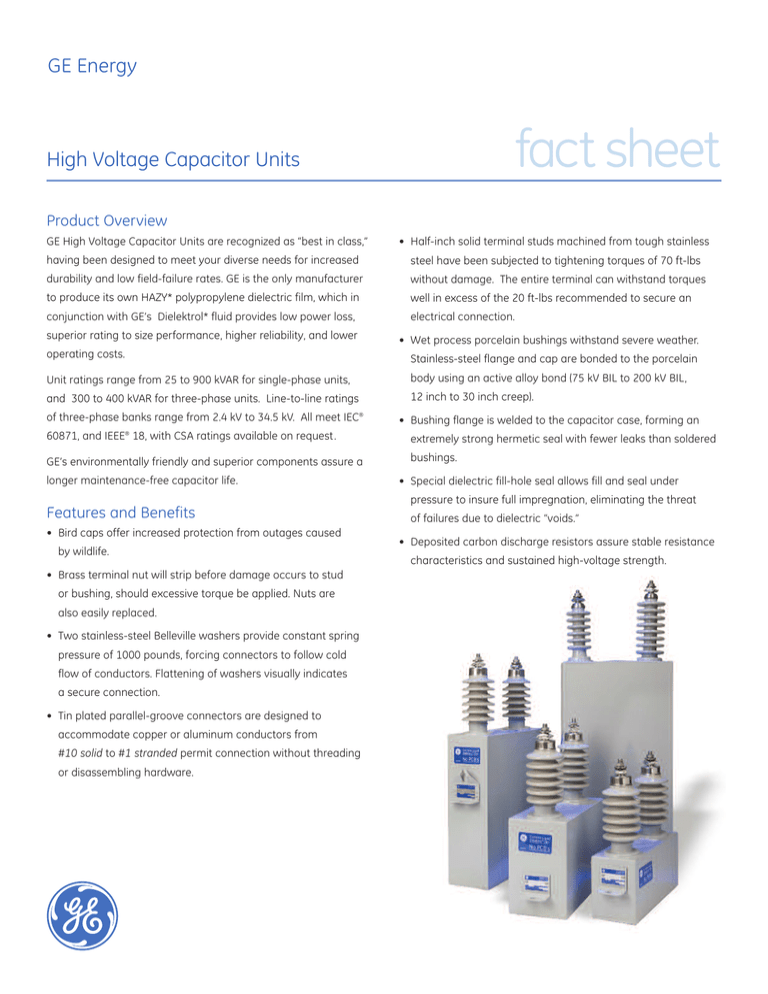
• Wet process porcelain bushings withstand severe weather.
Stainless-steel flange and cap are bonded to the porcelain
Unit ratings range from 25 to 900 kVAR for single-phase units,
body using an active alloy bond (75 kV BIL to 200 kV BIL,
and 300 to 400 kVAR for three-phase units. Line-to-line ratings
12 inch to 30 inch creep).
of three-phase banks range from 2.4 kV to 34.5 kV. All meet IEC®
• Bushing flange is welded to the capacitor case, forming an
60871, and IEEE® 18, with CSA ratings available on request.
extremely strong hermetic seal with fewer leaks than soldered
GE’s environmentally friendly and superior components assure a
bushings.
longer maintenance-free capacitor life.
• Special dielectric fill-hole seal allows fill and seal under
pressure to insure full impregnation, eliminating the threat
Features and Benefits
• Bird caps offer increased protection from outages caused
by wildlife.
• Brass terminal nut will strip before damage occurs to stud
or bushing, should excessive torque be applied. Nuts are
also easily replaced.
• Two stainless-steel Belleville washers provide constant spring
pressure of 1000 pounds, forcing connectors to follow cold
flow of conductors. Flattening of washers visually indicates
a secure connection.
• Tin plated parallel-groove connectors are designed to
accommodate copper or aluminum conductors from
#10 solid to #1 stranded permit connection without threading
or disassembling hardware.
of failures due to dielectric “voids.”
• Deposited carbon discharge resistors assure stable resistance
characteristics and sustained high-voltage strength.
fact sheet
• Deposited carbon discharge resistors are designed to drain the
units’ residual charge to 50 volts or less within five minutes, or
75 volts or less in 10 minutes for some IEC applications. These
resistors contribute to safety for personnel during routine
inspection or maintenance.
• Ultrasonic welding of foils avoid the possibility of solder
damaging the rolls or insulation.
• Dead-soft annealed aluminum foil is processed to exacting
requirements to assure power factor stability.
• Film foil dielectric of HAZY polypropylene plastic made at our
capacitor plant facility provides a low loss, high reliability, long
life product.
• Roll-pack clamping bands secure packs to proper length with
• Stainless-steel case eliminated the need for protective repainting.
• Epoxy primer provides superior exterior coating adhesion to
the stainless-steel case.
• Urethane exterior coating aids heat dissipation, provides
pleasing appearance and exceeds ANSI C57.12.31 Pole-top
Transformer standards.
• Unpainted strip on underside of mounting bracket provides
automatic ground when capacitor is placed in rack or hanger.
• Assembled capacitor units are leak-tested using
a high-sensitivity helium mass spectrometer.
• Heavy-duty flush welded stainless-steel bottom with runners
gives superior strength and durability. Runners keep weld
seams from dragging on the ground.
no mechanical damage to the dielectric pad. Exact length
control compresses pack to precise design dimensions to
Application
assure adequate space factor and eliminate threat of failure
GE Energy capacitors can be applied on high-voltage power
due to dielectric voids.
transmission lines in both open stack racks and metal enclosed
• Stainless-steel mounting brackets are welded to case at
multiple points for extra strength.
• Many layers of high-dielectric-strength kraft paper insulate
capacitor rolls from case. This insulation raises the capacitor
Basic Insulation Level to that of distribution transformers of the
same voltage rating.
banks. These capacitors provide an economical source for:
• Voltage support
• VAR support
• Increased system capacity
• Improved power transfer capability
For more information about GE Energy's Service solutions,
visit www.ge.com/energy. You can also contact your GE
representative at energy.tdsolutions@ge.com.
* Trademark of General Electric Company.
IEEE is a registered trademark of the Institute of Electrical Electronics Engineers, Inc.
IEC is a registered trademark of Commission Electrotechnique Internationale.
Copyright © 2009 General Electric Company. All rights reserved.
GEA17811 (07/2009)


