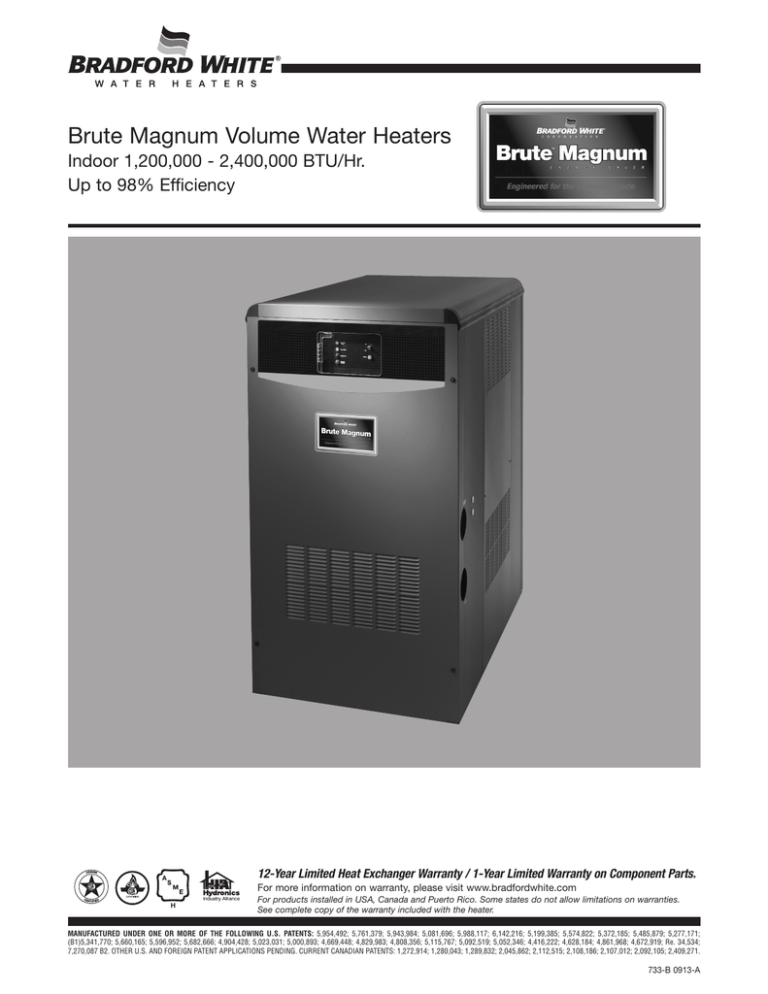
Brute Magnum Volume Water Heaters
Indoor 1,200,000 - 2,400,000 BTU/Hr.
Up to 98% Efficiency
12-Year Limited Heat Exchanger Warranty / 1-Year Limited Warranty on Component Parts.
For more information on warranty, please visit www.bradfordwhite.com
For products installed in USA, Canada and Puerto Rico. Some states do not allow limitations on warranties.
See complete copy of the warranty included with the heater.
MANUFACTURED UNDER ONE OR MORE OF THE FOLLOWING U.S. PATENTS: 5,954,492; 5,761,379; 5,943,984; 5,081,696; 5,988,117; 6,142,216; 5,199,385; 5,574,822; 5,372,185; 5,485,879; 5,277,171;
(B1)5,341,770; 5,660,165; 5,596,952; 5,682,666; 4,904,428; 5,023,031; 5,000,893; 4,669,448; 4,829,983; 4,808,356; 5,115,767; 5,092,519; 5,052,346; 4,416,222; 4,628,184; 4,861,968; 4,672,919; Re. 34,534;
7,270,087 B2. OTHER U.S. AND FOREIGN PATENT APPLICATIONS PENDING. CURRENT CANADIAN PATENTS: 1,272,914; 1,280,043; 1,289,832; 2,045,862; 2,112,515; 2,108,186; 2,107,012; 2,092,105; 2,409,271.
733-B 0913-A
Brute Magnum Volume Water Specifications
Dimensions shown in inches mm
6 /16
160
5
E
3 /4
95
3
C
D
G
5
127 H
13
330
F
4 1/2
114
17 1/4
438
B
A
Dimensions
Model
Number
BRHHV1200
BRHHV1600
BRHHV2000
BRHHV2400
Model
Number
BRHHV1200
BRHHV1600
BRHHV2000
BRHHV2400
A
Depth
B
Width
C
in.
55
55
55
55
in.
341/2
341/2
341/2
341/2
in.
53
53
53
53
in.
48
48
48
48
in.
653/4
653/4
653/4
653/4
in.
8
8
8
8
in.
341/4
341/4
341/4
32
A
Depth
B
Width
C
Floor to
Air
Inlet
D
E
F
G
mm.
1397
1397
1397
1397
mm.
876
876
876
876
mm.
1346
1346
1346
1346
mm.
1219
1219
1219
1219
D
E
mm.
1670
1670
1670
1679
F
mm.
203
203
203
203
G
mm.
870
870
870
813
H
Vent
Conn.
Air
Inlet
Conn.
Water
Conn.
in.
181/4
181/4
181/4
181/4
in.
6
6
7
10
in.
6
8
8
8
in.
21/2
21/2
3
3
H
Floor to
Flue
Conn.
Vent
Conn.
Air
Inlet
Conn.
Water
Conn.
mm.
464
464
464
464
mm.
152
152
178
254
mm.
152
203
203
203
mm.
64
64
72
72
Gas Conn.
Control Packages
Std.,
A, F
B
B
Nat./LP
Nat.
LP
NPT
NPT
NPT
in.
in.
in.
1
11/2
11/2
11/2
2
2
2
2
11/2
2
2
11/2
Gas Conn.
Control Packages
Std.,
A, F
B
B
Nat./LP
Nat.
LP
NPT
NPT
NPT
mm.
mm.
mm.
25
38
38
38
51
51
38
51
51
38
51
51
Brute Magnum Volume Water Specifications
1 2 3 4
B R H H
5
V
6 7 8 9
10
11
12
13
14
15
16
SERIES
USAGE
SIZE
FUEL
ALTITUDE
LOCATION
V
1200
1600
2000
2400
N
P
A
I
FIRING
MODE
HEAT
EXCHANGER
OPTIONS
CODE
PUMP
OPTIONS
F
E
F
X
A
B
F
N
H
S
Model Character Designation
(1-4) Model Series Designation
BRHH = Brute Magnum
(11) Altitude
A = 0-10,000 ft.
(5) Usage
V= Volume Water
(12) Location
I = Indoor
(6-9) Size
1200 = 1,200,000
1600 = 1,600,000
2000 = 2,000,000
2400 = 2,400,000
BTU/Hr.
BTU/Hr.
BTU/Hr.
BTU/Hr.
(13) Firing Mode
F = Modulating
input
input
input
input
(14) Heat Exchanger
E = Glass Lined Steel with
Copper Tubes
F = Glass Lined Steel with
Cupronickel Tubes
(10) Fuel
N = Natural Gas
P = Propane
(15) Options
X = Standard, meets CSD-1, CA, FM,
A = Control Pack A: CSD-1, CA, FM, Alarm Bell (Instead of
dry contacts)
B = Control Pack B: CSD-1, CA, FM, Alarm Bell (Instead of
dry contacts, normally open vent valve, mounted safety
w/proof of closure and solenoid safety valve)
F = Non CSD-1
(16) Pump Options
N = Pump Mounted (Normal Water Conditions)
H = Pump Mounted (Hard Water Conditions, N/A for 2400)
S = Pump Mounted (Soft Water Conditions)
Sizing Data
Input
Model
Number
BRHHV1200
BRHHV1600
BRHHV2000
BRHHV2400
Output
Input
Boiler / Heater
Volts Phase Amps
Volts
Pump
Phase
Amps
120
230
Single
20
Single
20
Appliance
Surface
Left Side
Right Side
Top
Back
Front
Vent
Water Flow Data
Hard
Water
Flow Temp.
GPM Rise °F
108
20
169
17
189
19
216
20
Hard
Water
Model
Number
BRHHV1200
BRHHV1600
BRHHV2000
BRHHV2400
Flow Temp.
LPM Rise °C
409
11
641
9
717
11
818
11
Approx.
Shipping
Weight
lbs.
1420
1465
1495
1550
Approx.
Shipping
Weight
kg.
644
665
678
703
NOTES:
Output shown is based on certification test
standards. The efficiency of this unit will increase with
lower return water temperature and/or lower
modulating point, which will alter the output of the
Brute Magnum.
Clearances
Electrical Data
Model
Number
BRHHV1200
BRHHV1600
BRHHV2000
BRHHV2400
Output
Hi-Fire Hi-Fire Hi-Fire Hi-Fire Lo-Fire Lo-Fire Lo-Fire Lo-Fire
BTU/Hr.
kW
kW
kW
kW
BTU/Hr.
BTU/Hr.
BTU/Hr.
1,200,000 352
1,068,000 313
300,000
88
267,000
78
1,600,000 469
1,424,000 417
400,000
117
356,000
104
2,000,000 586
1,780,000 521
499,750
146
444,775
130
2,400,000 703
2,140,000 627
600,000
176
535,000
157
Normal
Water
Soft
Water
Flow Temp. Flow Temp.
GPM Rise °F GPM Rise °F
86
25
72
30
137
21
93
31
157
23
35
103
173
25
30
144
Normal
Water
Soft
Water
Flow Temp. Flow Temp.
LPM Rise °C LPM Rise °C
327
14
273
17
519
12
352
17
593
13
389
19
654
14
545
17
Note: Soft water: 1 to 7.5 grains per gallon. Normal
water: 7.6 to 17 grains per gallon. Hard water: More than
17 grains per gallon.
Important Note: water flow shown is calculated based
on certification standards. The efficiency of this unit will
increase with lower return water temperature and/or
lower modulation point, which will lead to varying
temperature rise.
Required Clearance from Suggested Service
Combustible Material
Access Clearance
in.
mm.
in.
mm.
1
24
25
610
1
24
25
610
1
24
25
610
1
36
25
914
1
36
25
914
Per UL1738 venting system supplier's instructions
Recovery Data
GPH Recovery at Degree Rise
Model
Number
40°F
50°F
60°F
70°F
80°F
90°F
100°F
120°F
140°F
BRHHV1200
BRHHV1600
BRHHV2000
BRHHV2400
3241
4322
5402
6483
2593
3457
4322
5186
2161
2881
3601
4322
1852
2470
3087
3704
1621
2161
2701
3241
1441
1921
2401
2881
1297
1729
2161
2593
1080
1441
1801
2161
926
1235
1543
1852
LPH Recovery at Degree Rise
Model
Number
BRHHV1200
BRHHV1600
BRHHV2000
BRHHV2400
22°C
28°C
33°C
39°C
44°C
50°C
56°C
67°C
78°C
12,252 9802
16,336 13,069
20,420 16,336
24,504 19,603
8168
10,891
13,613
16,336
7001
9335
11,669
14,002
6126
8168
10,210
12,252
5445
7261
9076
10,891
4901
6534
6168
9802
4084
5445
6807
8168
3501
4667
5834
7001
Important Note: recovery shown is calculated based on efficiencies from certification
standards. The efficiency of this unit will increase with lower return water temperature
and/or lower modulation point, which will lead to higher recovery.
Brute Magnum Volume Water Specifications
Standard Features
■ 4 sizes, 1,200-2,400 MBH input
■ Efficiencies of up to 98%
■ Low NOx operation - less than 10ppm
■ Finned copper tube 2-pass heat exchanger
with ASME 160 psi rating
■ Glass lined header & cover plate
■ Secondary stainless steel condensing heat
exchanger
■ Stainless steel condensate collection
systems
■ 125 psi relief valve
■ Full modulation firing capabilities down to
25% of input
■ Variable speed, sealed combustion blower
with spark-resistant motor & DC direct drive
■ Proportional gas valve/regulator for
seamless modulation
■ High & low gas pressure switches
■ Redundant safety gas valve, manual shut off
valve
■ Leak test valve
■ Low fire start with time delay
■ Washable combustion air filter
■ May use ducted outside air, or room air for
combustion
■ Hot surface ignition
■ Premix stainless steel burner with sealed
combustion
■ Cat. IV venting, horizontal or vertical
terminations
■ Low NOx – less than 10ppm
■ Boiler circulating pump, factory mounted
and wired inside cabinet
■ Side-mounted supply and return water
connections
■ Temperature / pressure gauge
■ Power on/off switch
■ Diagnostic Indicator lights for: Power On,
Call for Heat, Pre-Purge, Burner On, Ignition
Failure
■ Internal/External 0-10VDC control selector
■ Dry alarm contacts
■ CSD-1 complaint
■ Adjustable, manual reset high limit
■ Water flow switch
■ Manual reset low water cutoff with test
switch
■ Air pressure switch
■ Condensate Overflow Protection Switch
Factory Mounted Options
■ Factory-installed LON card for communicating inlet / outlet / mixing system water temperatures, extra temperature (user-chosen), low
mixing system temperature alarm, burner on/off status
■ Control Pack A: adds 4" alarm bell (instead of dry contacts) and normally open vent valve to the standard unit.
■ Control Pack B: adds 4" alarm bell (instead of dry contacts), normally open vent valve, motorized safety valve with proof of closure, and
solenoid safety valve to the standard unit.
■ Control Pack F: same as the standard unit, but with non-CSD-1 ignition control (three trials for ignition).
Accessories for Field Mounting
■ Side-wall vent terminal for horizontal venting
■ Side-wall combustion air terminal for horizontal ducted air
■ Valve Heater Kit (req'd below 15°F (-9°C)- control packs B and E require 2)
■ Neutralizer kit
■ Condensate pump
■ Neutralizer kit with condensate pump
Sample Specification
The water heater shall be a Bradford White Brute Magnum Model BRHHV____, modulating, sealed combustion, Category IV (condensing) water heater with a modulating input and output
rate as shown on the schedule, with a recovery rate of _____gph (_____L/hr) for a 100°F (56°C) water temperature rise. The water heater shall have a thermal efficiency of 89.2%.The
water heater shall be design certified to comply with the current edition of the Harmonized ANSI Z21.10.3 / CSA 4.3 Standard for Gas-Fired Water Heaters. The water heater shall be
designed and constructed in accordance with the ASME Water heater & Pressure Vessel Code, Section IV requirements for 160 psi (1103 kPa) working pressure.
The water heater shall be capable of normal operation and full input with supply gas pressure as low as 4" (107mm) w.c. Water heater shall automatically compensate for large fluctuations
of gas supply pressure between 4" (107mm) w.c. and 13"(330mm) w.c.
The primary water tube heat exchanger shall be a vertical round design, with 7/8" (22mm) inner diameter intergral finned copper tubes.The tubes shall be rolled directly into lined ASME
headers rated for 160 psi (1103 kPa) working pressure. The secondary condensing heat exchanger shall be a stacked horizontal design with 7/8" (22mm) inner diameter finned stainless
steel tubes. The tubes shall be welded into stainless steel ASME headers rated for 160 psi (1103 kPa) working pressure. All waterways shall be non-ferrous. The heat exchangers shall
be a low water volume design. All gaskets shall be non-metallic, and separated from the combustion chamber by at least 3.5" (89mm) to eliminate deterioration from heat. Headers shall
have covers permitting visual inspection and cleaning of all internal surfaces.
The heat exchanger shall be removable from the unit, without excessive disassembly of the heater’s combustion chamber.The water heater shall use a proven hot surface ignition with a
15 second pre-purge cycle to clear the venturi assembly and combustion chamber. The heater shall start in low fire, and remain in low fire for 15-seconds at the start of each cycle. The
heater shall be 120V, single phase, 20A.
The burner shall be cylindrical type with woven metal fiber to provide a cleaner, more complete fuel combustion and low NOx emission, not exceeding 10 PPM.
The water heater shall come complete with an inline mounted pump sized to provide the correct water flow rate for the heater and 30 ft. (9.1m) of full sized piping. Each unit shall be
furnished with an EM2 energy management monitor relay and pump timer. The timer shall bea high quality solid state electronic device. The device shall be user adjustable from 0.1 to
10 minutes for continued pump circulation after the call for heat has been satisfied, to remove residual heat from the unit.
Dimensions and specifications subject to change without notice in accordance with our policy of continuous product improvement.
Ambler, PA
For U.S. and Canada field service, contact your professional installer or local Bradford White sales representative.
Sales 800-523-2931 ● Fax 215-641-1670 / Technical Support 800-334-3393 ● Fax 269-795-1089 ● Warranty 800-531-2111 ● Fax 269-795-1089
International: Telephone 215-641-9400 ● Telefax 215-641-9750 / www.bradfordwhite.com
Sales / Technical Support 866-690-0961 / 905-238-0100 ● Fax 905-238-0105 / www.bradfordwhite.com
©2013, Bradford White Corporation. All rights reserved.
733-B-0913-A
Printed in U.S.A.

