BASIC ELECTRICAL
Series Resistance
OBJECTIVES
Define Series connection
Define a Series circuit
Calculate Series Resistive circuit
INTRODUCTION
The are several distinct ways to connect resistive loads together to make a circuit. In this lesson, one of
the ways will be covered (Series) as well as series resistance connections, series resistive circuits, and calculating total resistance for a series resistive circuit. This lesson will use “Resistors” as simple resistive components,
many other electronic components have resistance values and will follow the same methods as described for
Resistors.
Series Connection
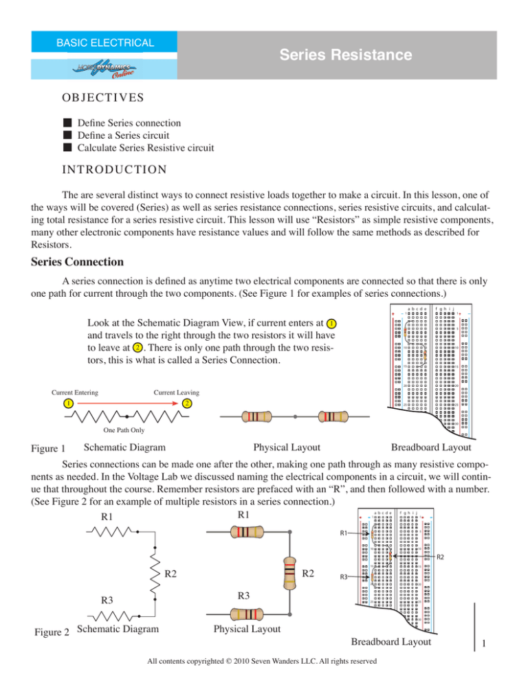
A series connection is defined as anytime two electrical components are connected so that there is only
one path for current through the two components. (See Figure 1 for examples of series connections.)
�������������
Look at the Schematic Diagram View, if current enters at 1
and travels to the right through the two resistors it will have
to leave at 2 . There is only one path through the two resistors, this is what is called a Series Connection.
Current Entering
Current Leaving
1
2
����������������
�
�
�
�
��
��
��
��
��
��
��
��
��
One Path Only
Figure 1
Schematic Diagram
Physical Layout
Breadboard Layout
Series connections can be made one after the other, making one path through as many resistive components as needed. In the Voltage Lab we discussed naming the electrical components in a circuit, we will continue that throughout the course. Remember resistors are prefaced with an “R”, and then followed with a number.
(See Figure 2 for an example of multiple resistors in a series connection.)
R1
R1
�������������
��
����������������
�
�
�
�
��
��
��
��
��
��
��
��
��
R2
R2
R3
R3
Figure 2 Schematic Diagram
Physical Layout
��
��
Breadboard Layout
All contents copyrighted © 2010 Seven Wanders LLC. All rights reserved
1
Series Circuit
The Resistive connections are typically the “LOAD” of an electrical circuit. To make a complete electrical circuit we need to add the rest of the components of a circuit. Remember an electrical circuit had four main
parts; the source, the circuit path, the load, and the control. The series connection we have discussed so far represents the Load and what type of path the circuit is. Figure 3 shows the rest of the components that make up a
Series Circuit. The load may have more than one electrical component and typically does. These examples have
three components in the “LOAD”.
Switches are typically shown in schematic diagrams
as open or unpressed if they are push-button type.
SW1
SW1
�����������������
����
����
R1
R1
B1
R2
R2
Schematic Diagram of Series Circuit
R3
�������
�������
R3
B1
Physical Diagram of Series Circuit
SW1 in the Physical Diagrams is a SPDT but is being
used as a SPST as in the schematic diagram, this is OK
to do.
��
��
��
��
��
��
��
��
��
�
�
����������������
�
��
�������
Figure 3
�������
�������������
SW1
��
�
��
B1
Physical Diagram of Series Circuit built on Breadboard
All contents copyrighted © 2010 Seven Wanders LLC. All rights reserved
2
Calculate Series Resistive circuit
The resistive value of a series circuit can be looked at as if it was just one total resistance. This means
the series circuit may have a R1, R2, and R3, but these resistances can be looked at as one “Total Resistance”.
The way R1, R2, and R3 can be mathematically converted to the Total Resistance (Rt) is to add the ohmeric
values of R1, R2, and R3 together to get Rt. See Figure 4 for the formula.
R1 + R2 + R3 ... = Rt
Figure 4
Example 1
200 Ω
200 Ω
200 Ω
Three 200Ω Resistors would look like a single 600Ω Resistor to the rest of the circuit.
600 Ω
Notice that the color for the first strip on the resistor has changed. In the
electronic component lesson these color bands or strips will be explained, it
should be noted know that the resistance is as labeled. (600 Ω)
The formula in Figure 4 can be used for any number of resistances in SERIES, this is indicated by the ...
in the formula. Example 2 shows a schematic diagram version of the simplification process.
Example 2
SW1
SW1
R1
300 Ω
B1
50 Ω
R2
B1
525 Ω
Rt
175 Ω
Circuit 1
R3
Circuit 2
300Ω + 50Ω + 175Ω = 525Ω
The battery and the switch would not see a difference between circuit 1 and circuit 2, it is said
that R1, R2, and R3 are equivalent (equal) to Rt. In the following lessons being able to simplify a circuit to its total resistance will be very important.
All contents copyrighted © 2010 Seven Wanders LLC. All rights reserved
3


