Circuit Analysis (Source Transform)
advertisement
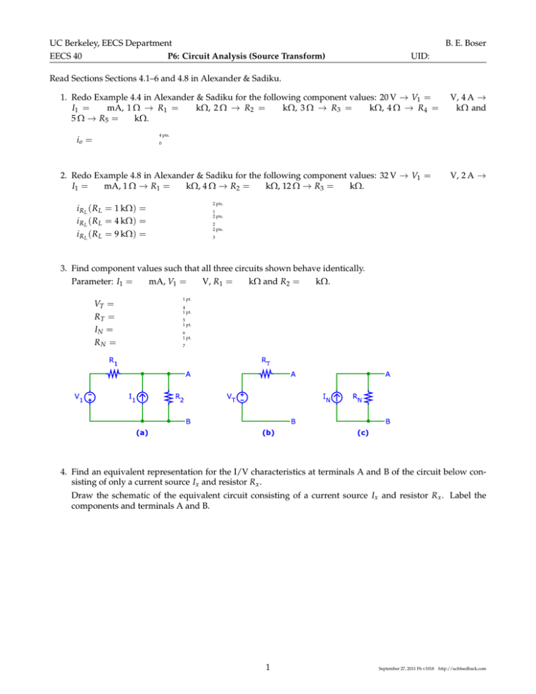
UC Berkeley, EECS Department EECS 40 P6: Circuit Analysis (Source Transform) B. E. Boser UID: Read Sections Sections 4.1–6 and 4.8 in Alexander & Sadiku. 1. Redo Example 4.4 in Alexander & Sadiku for the following component values: 20 V → V1 = I1 = mA, 1 Ω → R1 = kΩ, 2 Ω → R2 = kΩ, 3 Ω → R3 = kΩ, 4 Ω → R4 = 5 Ω → R5 = kΩ. V, 4 A → kΩ and 4 pts. io = 0 2. Redo Example 4.8 in Alexander & Sadiku for the following component values: 32 V → V1 = I1 = mA, 1 Ω → R1 = kΩ, 4 Ω → R2 = kΩ, 12 Ω → R3 = kΩ. V, 2 A → 2 pts. i R L ( R L = 1 kΩ) = i R L ( R L = 4 kΩ) = i R L ( R L = 9 kΩ) = 1 2 pts. 2 2 pts. 3 3. Find component values such that all three circuits shown behave identically. Parameter: I1 = VT = RT = IN = RN = mA, V1 = V, R1 = kΩ and R2 = kΩ. 1 pt. 4 1 pt. 5 1 pt. 6 1 pt. 7 4. Find an equivalent representation for the I/V characteristics at terminals A and B of the circuit below consisting of only a current source Ix and resistor R x . Draw the schematic of the equivalent circuit consisting of a current source Ix and resistor R x . Label the components and terminals A and B. 1 September 27, 2011 P6 v1018 http://ucbfeedback.com Calculate the values of Ix and R x for I1 = R3 = kΩ. Ix = Rx = mA, V2 = mA, R1 = kΩ, R2 = kΩ, and 1 pt. 8 1 pt. 9 5. Calculate the value of current i x . Parameter I1 = R3 = kΩ and R4 = kΩ. ix = V, I3 = mA, V2 = V, V3 = V, R1 = kΩ, R2 = kΩ, 12 pts. 10 6. For evaluation, circuit (a’) is temporarily connected to circuit (a) and the following measurements are taken with the ampère- and volt-meters shown in circuit (a’) (for different values of R L ): i) ii) V= V= V V A= A= mA mA a) Determine the values of VT and R T such that circuits (a) and (b) behave identically. opt. VT = 11 opt. RT = 12 b) The apprentice is asked to verify the measurement, but inadvertently mixes up the volt- and ampèremeters. What readings does he get when redoing measurement (i) above? Use the values from part (a) for VT and R T . opt. V= 13 opt. A= 14 2 September 27, 2011 P6 v1018 http://ucbfeedback.com 7. Find component values such that all three circuits shown behave identically. Given: I1 = R1 = kΩ and R2 = kΩ. i2 = V, opt. VT = RT = IN = RN = 8. Find the value of current i2 . Parameters: V1 = R4 = kΩ. Hint: Use source transformation. mA, V1 = 15 opt. 16 opt. 17 opt. 18 V, I1 = mA, R1 = kΩ, R2 = kΩ, R3 = kΩ, opt. 19 9. Find the Thevenin equivalent for port A-B in the circuit shown below. Use the following component values: resistors kΩ, voltage sources V, current sources mA. VT = RT = opt. 20 opt. 21 3 September 27, 2011 P6 v1018 http://ucbfeedback.com Password: 4 September 27, 2011 P6 v1018 http://ucbfeedback.com
