ge 60 data sheet

DATA SHEET GE 60
STEREO GRAPHIC EQUALIZER
General Description
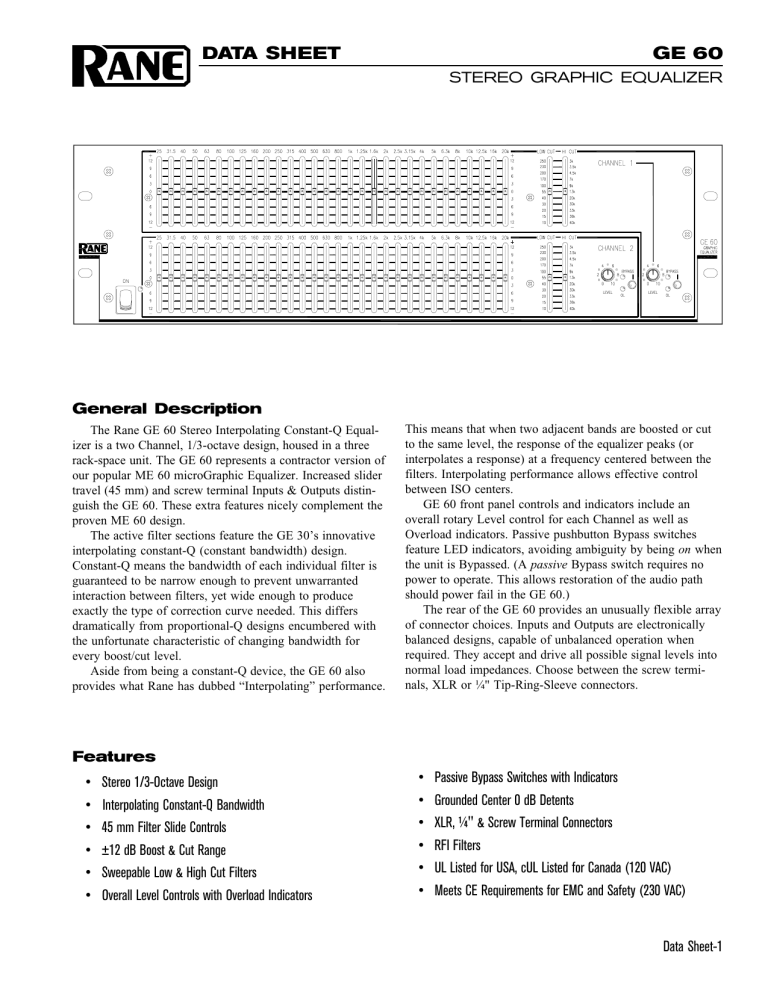
The Rane GE 60 Stereo Interpolating Constant-Q Equalizer is a two Channel, 1/3-octave design, housed in a three rack-space unit. The GE 60 represents a contractor version of our popular ME 60 microGraphic Equalizer. Increased slider travel (45 mm) and screw terminal Inputs & Outputs distinguish the GE 60. These extra features nicely complement the proven ME 60 design.
The active filter sections feature the GE 30’s innovative interpolating constant-Q (constant bandwidth) design.
Constant-Q means the bandwidth of each individual filter is guaranteed to be narrow enough to prevent unwarranted interaction between filters, yet wide enough to produce exactly the type of correction curve needed. This differs dramatically from proportional-Q designs encumbered with the unfortunate characteristic of changing bandwidth for every boost/cut level.
Aside from being a constant-Q device, the GE 60 also provides what Rane has dubbed “Interpolating” performance.
This means that when two adjacent bands are boosted or cut to the same level, the response of the equalizer peaks (or interpolates a response) at a frequency centered between the filters. Interpolating performance allows effective control between ISO centers.
GE 60 front panel controls and indicators include an overall rotary Level control for each Channel as well as
Overload indicators. Passive pushbutton Bypass switches feature LED indicators, avoiding ambiguity by being on when the unit is Bypassed. (A passive Bypass switch requires no power to operate. This allows restoration of the audio path should power fail in the GE 60.)
The rear of the GE 60 provides an unusually flexible array of connector choices. Inputs and Outputs are electronically balanced designs, capable of unbalanced operation when required. They accept and drive all possible signal levels into normal load impedances. Choose between the screw terminals, XLR or ¼" Tip-Ring-Sleeve connectors.
Features
• Stereo 1/3-Octave Design
• Interpolating Constant-Q Bandwidth
• 45 mm Filter Slide Controls
• ±12 dB Boost & Cut Range
• Sweepable Low & High Cut Filters
• Overall Level Controls with Overload Indicators
• Passive Bypass Switches with Indicators
• Grounded Center 0 dB Detents
• XLR, ¼" & Screw Terminal Connectors
• RFI Filters
• UL Listed for USA, cUL Listed for Canada (120 VAC)
• Meets CE Requirements for EMC and Safety (230 VAC)
Data Sheet-1
GE 60
STEREO GRAPHIC EQUALIZER
Features and Specifications
Parameter
Equalizer:
..........Channels
..........Bands
..........Type
..........Accuracy
..........Travel
..........Range
Inputs:
..........Type
..........Connectors
..........Impedance
..........Maximum Level
Outputs:
..........Type
..........Connectors
..........Impedance
..........Maximum Level
Overall Gain Range
RFI Filters
Passive Bypass Switches
Overload LED Threshold
Low Cut Filter
High Cut Filter
Frequency Response
THD+Noise
IM Distortion (SMPTE)
Signal-to-Noise Ratio
Channel Separation
Common Mode Rejection
Maximum Power
Line Voltage:
..........Domestic
..........Export
Unit: Agency Listing
..........120 VAC model
Specification
Two
(2x30) 1/3-Octave ISO Spacing
Interpolating Constant-Q
3
45
±12
Active Balanced
XLR, ¼" TRS & Screw Terminals
>20k Balanced
21
Active Balanced
XLR, ¼" TRS & Screw Terminals
200 Balanced
+22 Balanced
Off to +8 Balanced
Yes
Yes
4
10-250 Hz, 12 dB/octave
3k-40 kHz, 12 dB/octave
20-20 kHz
10-40 kHz
0.009
0.005
re +20 dBu/+4 dBu
115/95
75
40
12
105-130 VAC, 50/60 Hz
205-250 VAC, 50 Hz
..........230 VAC model
..........Construction
..........Size
..........Weight
Shipping:
..........Size
..........Weight
UL cUL (Canada)
CE-EMC EN55013 & EN55020
CE-Safety EN60065
All Steel
5.25"H x 19"W x 8.5"D (3U)
11 lb
11" x 23" x 16"
13 lb
Limit Units Conditions/Comments
1
2
3
1
1%
1
% mm dB ohms dBu
1% ohms
1 dBu
-0/+4 dB
1
3% dB
Hz
3%
±0.5
Hz dB
+0/-3 dB
.002
%
.003
% dB dB dB
W
From 25 Hz to 20 kHz
Smooth combining
Center frequency
Positive grounded center detent
600 ohms
Sliders centered
Below clipping
Butterworth
+4 dBu, 20-20 kHz
60 Hz/7 kHz, 4:1, +4 dBu
20 kHz noise BW; balanced out
Sliders centered, unity gain
1 kHz
1 kHz
UL 813 (file E104174)
C22.2 (file E193164)
EMC directive 89/336/EEC
LV directive 73/23/EEC
(13.3 cm x 48.3 cm x 21.6 cm)
(5.0 kg)
(27.9 cm x 58.4 cm x 40.6 cm)
(5.9 kg)
Note: 0 dBu = 0.775 Vrms
Data Sheet-2
GE 60 Block Diagram
GE 60
STEREO GRAPHIC EQUALIZER
(Channel 1 Shown, Channel 2 Identical)
Application Information
The GE 60 offers the same high quality interpolating constant-Q performance as its relative, the GE 30. No compromises or trade-offs exist in selecting the GE 60. It is constructed using only precision audio-grade components and advanced integrated circuits, all assembled onto mil-spec glass-epoxy printed circuit boards.
The adjustable filters are useful when it is desirable to band limit the audio signal. For instance, restricting high frequencies to match the incoming signal usually produces the quietest system. And a common use for the Low Cut filter is limiting the signal going to 70 volt speaker systems. Often low frequencies saturate the loudspeaker transformers.
Restricting these signals greatly improves system intelligibility. Full bandwidth use requires positioning both sliders to their lower limits. This effectively removes the filters and guarantees 20-20 kHz ±0.5 dB performance.
The interpolating constant-Q performance of the GE 60 arose from the sound professional’s need for greater control with less interaction than previously possible with conventional equalizers. Truth in slider position became a requirement. The curve traced out by the slider positions on constant-Q designs indeed represents the actual changes to the frequency response. On conventional designs they do not.
Combine this feat with the Rane developed “interpolating” characteristic and you have a tool without peer.
The GE 60 goes one step further toward being the best device for any application. It offers the choice of all common audio input and output connectors. The inclusion of XLR, ¼" and screw terminal Input and Output connectors ensures acceptance in all installations.
While designed primarily for permanently installed systems, this does not mean that its mechanical integrity is inferior to other Rane products. All Rane signal processing gear can withstand the rigors of being thrown into the back of a ’68 Pontiac station wagon by their line cords and transported from one bar to another.
CONSTANT-Q DETAILS
Traditional equalizer designs present a problem in that the filter’s level control is actually a part of the filter. Consequently, whenever the slider is moved, the bandwidth changes. The output exhibits the desired bandwidth only at full boost or cut. It degrades to as much as two octaves at moderate slider settings. Responding to this dilemma, Rane developed a topology ensuring constant filter bandwidth
(“Q”) at all slider positions.
Another important advantage of constant bandwidth is reduction of adjacent filter overlap. Conventional designs exhibit excessive overlap at moderate slider settings. Adjusting one slider affects the adjacent neighbors, requiring readjustments to each. Filter overlap in Rane equalizers is dramatically less, reducing the need for constant readjustment of adjacent sliders. This means more effective equalization in significantly less time.
INTERPOLATING DETAILS
Today’s sophisticated acoustic measurement tools show exact trouble spots. Often these lie between ISO centers. An interpolating equalizer allows correction for these response errors by producing a smooth peak or dip between (i.e., it interpolates, or inserts between) any two adjacent frequency sliders when they are raised or lowered the same amount.
Non-interpolating responses exhibit a slight dip (ripple) under similar conditions.
Data Sheet-3
GE 60
STEREO GRAPHIC EQUALIZER
Rear Panel
Architectural Specifications
The graphic equalizer shall be a two channel model of interpolating constant-Q design to minimize interactions between adjacent bands, and shall occupy three rack spaces
(3U). Each channel shall have thirty (30) frequency bands located on standard ISO center frequencies. Each band shall have a bandwidth of 1/3-octave. A detented and positively grounded 0 dB point shall be provided on 45 mm linear sliders with dust dams.
Low and high cut filters shall be provided with 12 dB/ octave slopes and adjustable corner frequencies. A rotary overall level control shall be provided with a range from Off to +8 dB of gain when used in balanced mode.
The inputs and outputs shall be active balanced/unbalanced designs terminated with XLR, ¼" TRS (tip-ringsleeve), and screw terminals. The outputs shall have equal output impedances. RFI filters shall be provided. The unit shall provide a passive bypass feature for each channel requiring no power to operate. LEDs shall be provided to indicate overload and bypass conditions.
The 120 VAC 50/60 Hz model shall be UL and cUL listed and operate by means of its own built-in power supply. The
230 VAC 50 Hz model shall meet the European requirements for EMC and safety and carry the CE mark of compliance.
The unit shall be constructed entirely from cold-rolled steel.
The unit shall be a Rane GE 60 Graphic Equalizer.
Available Accessories
• SC 5.2 Security Cover
References
1. D. Bohn, “Constant-Q Graphic Equalizers,” Rane Note 101 , (1982).
2. D. Bohn, “A New Generation of Filters,” Sound and Video Contractor , vol. 2, pp. 36-39 (Feb. 1984).
3. T. Pennington, “Constant-Q,” Studio Sound , vol.27, pp. 82-85 (Oct. 1985).
4. D. Bohn, “Constant-Q Graphic Equalizers,” J. Audio Eng. Soc.
, vol. 34, pp. 611-626 (September 1986).
5. D. Bohn, “Exposing Equalizer Mythology,” Rane Note 115 , (1986).
6. D. Bohn, “Operator Adjustable Equalizers: An Overview,” Rane Note 122 , (1990).
©Rane Corporation 10802 47th Ave. W., Mukilteo WA 98275-5098 TEL (425)355-6000 FAX (425)347-7757 WEB http://www.rane.com
Data Sheet-4
All features & specifications subject to change without notice. DOC 103081 PN 06707 2-98


