Technical Note
Mass Flow Sensors: Mass Flow versus Volumetric Flow and
Flow Rate Unit Conversions
1.0
Introduction
This technical note explains the following:
How mass flow is measured with volumetric units at
standard conditions.
How to convert between volumetric units at standard
conditions of 0 ºC, 1 atm, and nonstandard temperature
and pressure conditions.
How to convert between volumetric units at standard
conditions of 0 ºC, 1 atm, and an alternative standard
temperature and pressure conditions.
How to convert from volumetric units to mass units.
Honeywell mass flow sensors use a silicon sense die
construction known as a microbridge to measure the rate of
mass transfer in a fluid.
Mass flow is a dynamic mass/time unit measured in grams per
minute. It is common in the industry to specify mass flow in
terms of volumetric flow units at standard (reference)
conditions. By referencing a volumetric flow to a standard
temperature and pressure, an exact mass flow (g/min) can be
calculated from volumetric flow.
The temperature and pressure reference conditions of the
volumetric unit do not imply nor do they require the pressure
and temperature conditions of the measured fluid to be the
same; they are simply part of the volumetric unit that is
required to specify mass from a measured volume.
Honeywell mass flow sensors are generally specified as having
volumetric flow units at standard reference conditions of 0°C
and 1 atm. This is indicated on volumetric units with the "S"
prefix. For example:
SCCM
"Standard Cubic Centimeters (per) Minute"
Reference Conditions: 0 °C, 1 atm
SLPM
"Standard Liters (per) Minute"
Reference Conditions: 0 °C, 1 atm
Sensing and Control
If a certain application requires nonstandard reference
conditions, the units will be specified in the device datasheet
without the “S” prefix and the reference conditions will be
called out. The “@” symbol will be used to indicate the
volumetric unit reference conditions for temperature and flow.
For example:
CCM @ 21°C, 101.325 kPa
LPM @ 20 °C, 1013.25 mbar
When designing an application around a mass flow sensor, it is
critical to use consistent reference conditions for volumetric
units throughout the system. There is no industry standard for
the reference conditions indicated by “SCCM” or “SLPM”, they
must be explicitly determined.
Consider a Honeywell mass flow sensor which has output
calibrated for a full scale of 1000 SCCM. If this sensor is used
in a system with a mass flow controller that has a Full Scale of
1000 SCCM (defined by the manufacturer as using a reference
condition of 25°C, 1 atm), then without converting units, the
system error will be more than 9% of reading.
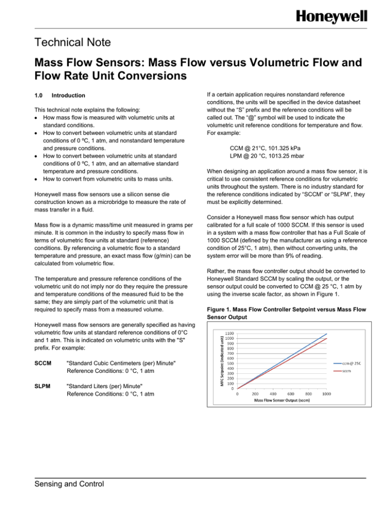
Rather, the mass flow controller output should be converted to
Honeywell Standard SCCM by scaling the output, or the
sensor output could be converted to CCM @ 25 °C, 1 atm by
using the inverse scale factor, as shown in Figure 1.
Figure 1. Mass Flow Controller Setpoint versus Mass Flow
Sensor Output
Mass Flow versus Volumetric Flow and Flow Rate Unit
Conversions
2.0
Finding True Mass Flow (g/min) from Volumetric
Flow (Q) Definitions
P = Pressure
3
V = Volume (cm )
n = Number of moles of gas
R = Gas constant .0821 (liters • atm/mole • °K) or
3
82.1 (cm • atm/mole • °K)
T = Absolute temperature in Kelvin (°K)
3
ρ = Gas density (g/cm )
m = Mass in grams (g)
m = Mass flow (g/min)
^ = Mass flow (g/min)
m
Q = Volumetric flow
Qs = Volumetric flow at standard conditions (SCCM)
Equation 1
Using the Ideal Gas Law, PV = nRT, solve for:
Volume (V), or:
nRT
V=
P
Equation 2
Gas density is defined as:
ρ=
m
v
Equation 3
Substitute Equation 1 into Equation 2 to redefine gas density:
mP
ρ=
nRT
Equation 4
Mass flow is equal to density times volumetric flow rate:
m=ρ·Q
Equation 5
Redefine mass flow using gas density as derived from the
Ideal Gas Law. Substitute Equation 3 into Equation 4:
mP
· Qx
m=
nRT
Example 1
3
Assume a volumetric flow rate of Q = 200 cm /min of nitrogen
(N2) at standard temperature of 0 °C and 1 atm, and solve for
true mass flow (g/min):
Given:
3
Q = 200 cm /min
m = 28.0134 g in 1 mole of N2
n = 1 mole
P = 1 atm
3
R = 82.1 (cm • 1 atm)/(mole • °K)
T = 273.15 °K(0 °C)
Answer:
m = 0.2498 (g/min)
2 Honeywell
Sensing and Control
3.0
Finding Volumetric Flow (Q) from True Mass Flow
(g/min)
Microbridge products are specified in “standard” volumetric
flow (Qs) such as standard cubic centimeters per minute
(SCCM) or standard liters per minute (SLPM) which can be
translated into true mass flow as indicated above.
The microbridge sensor is a mass flow device rather than a
volumetric one. At a constant mass flow, the microbridge
device will give the same output even if there are temperature
or pressure changes. Because the microbridge sensor senses
mass flow, confusion may result when mass flow sensors are
used with volumetric devices, such as rotometers or pith-ball
indicators. Accurate mass flow calculations for volumetric
devices require consideration of both temperature and
pressure ranges.
At varying temperatures and pressures, these other volumetric
devices indicate different flow rates than those indicated by
microbridge sensors. Simple calculations can be used to show
the relationship between mass flow and “nonstandard”
volumetric flow.
An AWM3100V with a mass flow rate of 0.2498 g/min
(200 SCCM) at the same pressure of 1.0 atm but at a different
temperature, 25 °C, has a 5 Vdc output voltage, indicating a
standard flow rate(Qs) of 200 SCCM. The rotometer, however,
would indicate a nonstandard volumetric flow rate, (Q).
Use Equation 5 to rearrange the formula for the volumetric flow
value to calculate the rotometer nonstandard volumetric flow
rate.
Equation 6
Q=
nRT
·m
mP
Use the following given values to calculate volumetric flow rate
3
(Q). Multiply the R value by 1000 to convert the number to cm :
Given:
^
m = 0.2498 (g/min)
m = 28.0134 grams in 1 mole of N2
n = 1 mole
P = 1.000 atm
3
R = 82.1 (cm • 1 atm)/(mole • °K)
T = 273.15 °K(0 °C) + 25 °C = 298.15 • °K
3
Answer: Q = 218.26 cm /min
In this example, the standard volumetric flow rate (Qs) is
3
200 cm /min while nonstandard volumetric flow rate increases
3
to 218.26 cm /min.
Mass Flow versus Volumetric Flow and Flow Rate Unit
Conversions
This increase reflects the fact that as temperature increases,
gas expands, placing more distance between gas molecules.
More distance between molecules means less mass in a given
volume as temperature increases. If mass flow is kept
constant, and temperature increases, volume flow increases to
pass the same amount of mass (molecules) across the sensor
(see Figures 2 and 3).
Figure 2. Molecules at Cold Temperature: Mass Flow
Constant, Volumetric Flow Decreases
Mass
Flow
If mass flow is held constant over temperature and
pressure, then the following is true:
m s = mx
That is,
ms
mass flow, at standard conditions is equal to
mx
mass flow at nonstandard X conditions of temperature
and pressure.
Therefore,
mPx · Qx = mPs
nRTs
nRTx
Equation 7: Solving for Qx yields:
Sensor
Figure 3. Molecules at Hot Temperature: Mass Flow
Constant, Volumetric Flow Increases
Mass
Flow
Sensor
4.0
Finding volumetric Flow (Qx) from “Standard”
Volumetric Flow (QS):
Qx = Qs ·
Equation 7
Equation 7 calculates volumetric flow (Qx) at “X” conditions
from volumetric flow (Qs) at reference conditions of 0 °C and 1
atm.
Given:
Qs = 200 SCCM
Ps = 1 atm
Px = 1 atm
Ts = 273.15 °K (0 °C)
Tx = 298.15 °K (25 °C)
Answer:
Qx = Qs ·
Nonstandard volumetric flow can be found with standard
volumetric flow using the ratio of temperature and pressure at
referenced conditions (0 °C, 1 atm) versus “X” conditions of
temperature and pressure.
This method of determining volumetric flow eliminates the use
of gas density values at reference conditions (0°C, 1 atm)
versus “X” conditions of temperature and pressure.
FURTHER DEFINITIONS
Qx = Volumetric flow at X conditions of pressure and
temperature
Qs = Volumetric flow at standard conditions of 0 °C and 1 atm
Tx = Temperature at “X” conditions in °Kelvin (°K)
Ts = Temperature at standard conditions in °Kelvin (°K)
Px = Pressure at “X” conditions in °Kelvin (°K)
Ps = Pressure at standard conditions in °Kelvin (°K)
3 Honeywell
Sensing and Control
Ps Tx
·
Px Ts
Ps Tx
·
= 218.3 cm3/min
Px Ts
Mass Flow versus Volumetric Flow and Flow Rate Unit
Conversions
WARNING
WARNING
PERSONAL INJURY
MISUSE OF DOCUMENTATION
DO NOT USE these products as safety or emergency stop
devices or in any other application where failure of the
product could result in personal injury.
Failure to comply with these instructions could result in
death or serious injury.
The information presented in this technical note is for
reference only. DO NOT USE this document as a product
installation guide.
Complete installation, operation, and maintenance
information is provided in the instructions supplied with
each product.
Failure to comply with these instructions could result in
death or serious injury.
WARRANTY/REMEDY
Honeywell warrants goods of its manufacture as being free of
defective materials and faulty workmanship. Honeywell’s
standard product warranty applies unless agreed to otherwise
by Honeywell in writing; please refer to your order
acknowledgement or consult your local sales office for specific
warranty details. If warranted goods are returned to Honeywell
during the period of coverage, Honeywell will repair or replace,
at its option, without charge those items it finds defective. The
foregoing is buyer’s sole remedy and is in lieu of all other
warranties, expressed or implied, including those of
merchantability and fitness for a particular purpose. In no
event shall Honeywell be liable for consequential, special,
or indirect damages.
While we provide application assistance personally, through
our literature and the Honeywell web site, it is up to the
customer to determine the suitability of the product in the
application.
Specifications may change without notice. The information we
supply is believed to be accurate and reliable as of this printing.
However, we assume no responsibility for its use.
SALES AND SERVICE
Honeywell serves its customers through a worldwide network
of sales offices, representatives and distributors. For
application assistance, current specifications, pricing or name
of the nearest Authorized Distributor, contact your local sales
office or:
E-mail: info.sc@honeywell.com
Internet: sensing.honeywell.com
Phone and Fax:
Asia Pacific
+65 6355-2828
+65 6445-3033 Fax
Europe
+44 (0) 1698 481481
+44 (0) 1698 481676 Fax
Latin America
+1-305-805-8188
+1-305-883-8257 Fax
USA/Canada
+1-800-537-6945
+1-815-235-6847
+1-815-235-6545 Fax
Sensing and Control
Honeywell
1985 Douglas Drive North
Golden Valley, MN 55422
sensing.honeywell.com
008043-2-EN
November 2012
Copyright © 2012 Honeywell International Inc. All rights reserved.

