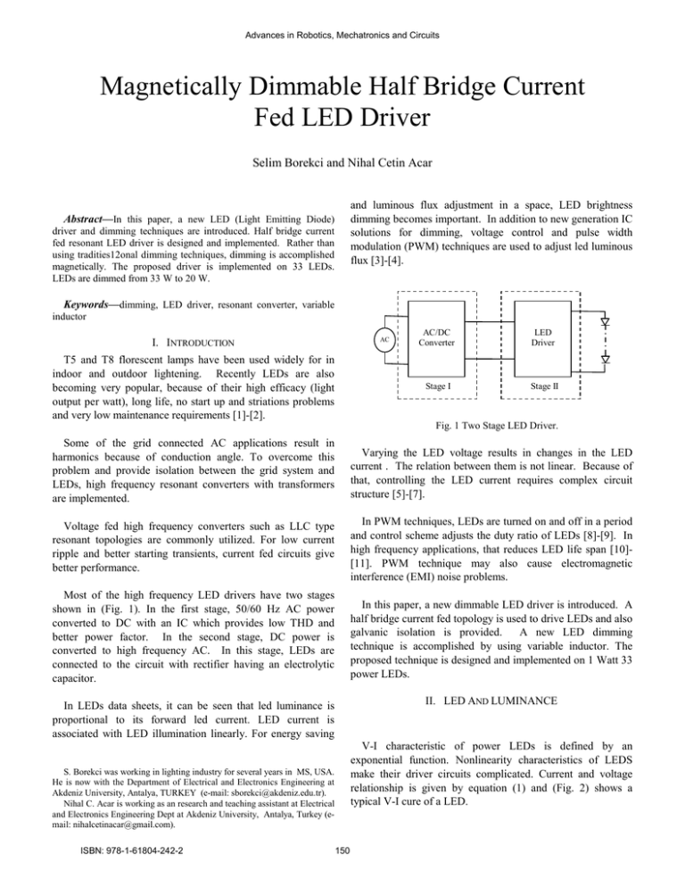
Magnetically Dimmable Half Bridge Current Fed LED Driver
advertisement

Advances in Robotics, Mechatronics and Circuits Magnetically Dimmable Half Bridge Current Fed LED Driver Selim Borekci and Nihal Cetin Acar and luminous flux adjustment in a space, LED brightness dimming becomes important. In addition to new generation IC solutions for dimming, voltage control and pulse width modulation (PWM) techniques are used to adjust led luminous flux [3]-[4]. Abstract—In this paper, a new LED (Light Emitting Diode) driver and dimming techniques are introduced. Half bridge current fed resonant LED driver is designed and implemented. Rather than using tradities12onal dimming techniques, dimming is accomplished magnetically. The proposed driver is implemented on 33 LEDs. LEDs are dimmed from 33 W to 20 W. Keywords—dimming, LED driver, resonant converter, variable inductor I. INTRODUCTION AC T5 and T8 florescent lamps have been used widely for in indoor and outdoor lightening. Recently LEDs are also becoming very popular, because of their high efficacy (light output per watt), long life, no start up and striations problems and very low maintenance requirements [1]-[2]. AC/DC Converter LED Driver Stage I Stage II Fig. 1 Two Stage LED Driver. Some of the grid connected AC applications result in harmonics because of conduction angle. To overcome this problem and provide isolation between the grid system and LEDs, high frequency resonant converters with transformers are implemented. Varying the LED voltage results in changes in the LED current . The relation between them is not linear. Because of that, controlling the LED current requires complex circuit structure [5]-[7]. Voltage fed high frequency converters such as LLC type resonant topologies are commonly utilized. For low current ripple and better starting transients, current fed circuits give better performance. In PWM techniques, LEDs are turned on and off in a period and control scheme adjusts the duty ratio of LEDs [8]-[9]. In high frequency applications, that reduces LED life span [10][11]. PWM technique may also cause electromagnetic interference (EMI) noise problems. Most of the high frequency LED drivers have two stages shown in (Fig. 1). In the first stage, 50/60 Hz AC power converted to DC with an IC which provides low THD and better power factor. In the second stage, DC power is converted to high frequency AC. In this stage, LEDs are connected to the circuit with rectifier having an electrolytic capacitor. In this paper, a new dimmable LED driver is introduced. A half bridge current fed topology is used to drive LEDs and also galvanic isolation is provided. A new LED dimming technique is accomplished by using variable inductor. The proposed technique is designed and implemented on 1 Watt 33 power LEDs. II. LED AND LUMINANCE In LEDs data sheets, it can be seen that led luminance is proportional to its forward led current. LED current is associated with LED illumination linearly. For energy saving V-I characteristic of power LEDs is defined by an exponential function. Nonlinearity characteristics of LEDS make their driver circuits complicated. Current and voltage relationship is given by equation (1) and (Fig. 2) shows a typical V-I cure of a LED. S. Borekci was working in lighting industry for several years in MS, USA. He is now with the Department of Electrical and Electronics Engineering at Akdeniz University, Antalya, TURKEY (e-mail: sborekci@akdeniz.edu.tr). Nihal C. Acar is working as an research and teaching assistant at Electrical and Electronics Engineering Dept at Akdeniz University, Antalya, Turkey (email: nihalcetinacar@gmail.com). ISBN: 978-1-61804-242-2 150 Advances in Robotics, Mechatronics and Circuits (1) where I Is VD n VT k T q There are several topologies for LED drivers as mentioned. Commonly used ones have two stages as shown in (Fig.1). In the first stage, AC grid is converted to DC. ICs are utilized for better power factor correction, THD and DC voltage regulation. The function of the first stage is a DC power supply. In the second stage, a LED driver is designed such that LED current results in desired led brightness. Dimming feature can also be added in this stage. diode forward current reverse bias saturation current diode forward voltage diode ideality factor thermal voltage Boltzman’s constant temperature charge on an electron III. PROPOSED SOLUTION The second stage is the focus of this research. A current fed half bridge converter shown in (Fig. 5) is implemented. In the circuit, two electrolytic capacitors Cdc are used to divide the DC voltage and two choke inductors Ldc takes place to regulate the current. A snubber capacitor C is used across power switches. There are two MOSFETs which are driven by IR2153. Magnetization impedance of the transformer Lp and resonant capacitor Cr determines the resonant frequency of the converter. The secondary voltage of the transformer is rectified by diodes. For the better output regulation, an electrolytic capacitor Co is placed in parallel with the LEDs. I( V) V Fig. 2 V & I Characteristic of a LED. As seen in (Fig. 3), there are two operating states; on and off. Figure (a) and (b) show the equivalent circuit of LED for on and off states respectively. Capacitive and resistive effects of LEDs during on and off are illustrated in (Fig. 3) as Con, Coff, Ron and Roff respectively. In the figure, Von represents the forward bias voltage of a LED. Ldc S1 Vdc/2 Ideal diode Con Ron Vin Coff Cdc C Cr + _ Roff Lp D3 D5 D4 D6 Ls C0 LED S2 Vdc/2 Von (a) D1 Vgs2 Vgs1 Cdc D2 (b) Fig. 3 Electrical Model of a LED. Ldc It is important that LED forward current determines the brightness of a LED. Figure 4 shows a typical relation between the forward current and relative luminous of a LED. LED luminous flux increases linearly with its current, while the voltage is almost constant. Therefore, the efficacy of LEDs can be assumed to be constant. Fig. 5 Proposed LED Driver. DC voltage, Vin, is applied to the half bridge current fed resonant converter. Primary and secondary voltages of the transformer are in sinusoidal shape. The peak value of the primer voltage for the first harmonic is calculated as (2) Number of LEDs m and forward voltage of selected LEDs Vled are determined at the beginning of the design. Therefore, the peak value of the secondary voltage can be obtained from equation (3). (3) When the primary and secondary voltages are known, the turn ratio of the transformer can be calculated as Fig. 4 Lamp Current versus LED Relative Luminous Flux. ISBN: 978-1-61804-242-2 151 Advances in Robotics, Mechatronics and Circuits (4) For high frequency applications, ferrite cores can be used. The saturation of the ferrite core is around 0.3 T. Better material can have higher saturation level. Selected frequency of the circuit, effective cross section area of the core, and the secondary voltage of the transformer determine the number of secondary turns as in equation (5). Multiplying the turn ratio with the number of secondary turns gives the number of primary turns. Lvrb Idc Fig. 6 Current Controlled Inductor. To dim LEDs, the inductor is integrated with the circuit given in (Fig. 5). Figure 7 shows the magnetically dimmable half bridge current fed LED driver. The current controlled inductor acts as an additional impedance in the secondary of the transformer and functions as ballast. (5) Selected magnetic core has its own effective permeability µeff, cross section area Aeff and effective magnetic length Leff. From the number of primary turns and core information, primer reactance can be calculated by equation (6). IV. EXPERIMENTAL AND SIMULATION RESULTS (6) The proposed circuit shown in (Fig. 7) is implemented on 33 LEDs. Resonant frequency is tune to 22 800 Hz and Mosfets are driven by 23 500Hz by IR2153. The circuit has 400 Vdc input and 100 Vdc output. Table I shows the components used in the implementation. The relationship between primary and secondary currents of the transformer is given in equation (7). Rp and Rs represent cupper losses for the primary and secondary respectively. kps is the coupling coefficient between primary and secondary windings. Vp and Vs are primary voltage and secondary voltages and Ip and Is are primary and secondary currents respectively. ω is the radian frequency of the circuit and RLed is the equivalent resistance of LEDs. Ldc S1 Vgs2 Vdc/2 Vin (7) Cdc D1 LVrb C Cr + _ Lp D3 D5 D4 D6 Ls C0 LED S2 where, Vdc/2 Vgs1 Cdc D2 , Ldc Fig. 7 Proposed LED Driver with dimming function. Table 1The List of components. Item Font 5mH 730uH 65uH 68nF 33 x1W Power Led 350mA, 100 lumen C 2nF 47uF 100uF Mosfets SK2605 Lvrb 1470uH-175uH To tune the resonant frequency, resonant capacitor Cr is selected from equation (6). (8) For dimming purpose, a current controlled inductor shown in (Fig. 6) is used. When dc control current is increased, the value of the inductor decreases. Detailed analyses of magnetically control inductor design can be found in [12]. ISBN: 978-1-61804-242-2 152 Advances in Robotics, Mechatronics and Circuits D3,D4,D5,D6 It can be seen that in the proposed approach, the switching frequency is kept constant and LEDs are not subjected to be on and off in a dimming period. MUR160 400V To meet the desired LED current, the value of inductance of the variable inductor is tuned by the control current. Figure 8 shows the relations between the control current and inductance value. When the inductor value is high, LEDs’ current becomes low and vice versa. Led Power & Idc 40,0 35,0 30,0 Watt 25,0 Lvrb mH Lvrb & Idc 20,0 15,0 1600 10,0 1400 5,0 1200 0,0 0,00 1000 0,20 0,40 0,60 0,80 1,00 1,20 1,40 1,60 Idc 800 600 Fig. 11 LEDs Power vesus Control Current. 400 200 0 0,00 0,20 0,40 0,60 0,80 1,00 1,20 1,40 Zero voltage switching is also accomplished with the proposed technique. While the body diode is in forward bias, MOSFET becomes on. As an example, 350 mA led current, drain current and drain source voltage of upper MOSFET are shown in (Fig. 12). 1,60 Idc Fig. 8 Inductance Variation with Control Current. With the proposed technique, lamp current is changed from 215 mA to 350 mA. The waveforms of 215mA and 350mA LED currents and their voltages are illustrated in (Figs 9 and 10) respectively. Fig. 12 LED current, Drain Current and Drain Source Voltage of MOSFET. V. CONCLUSION Fig. 9 LED Current and Voltage for Low Power. A unique dimmable current fed half bridge led driver is proposed in this study. Dimming is accomplished magnetically to meet desired led luminous flux. The proposed circuit is implemented on 33x1W LEDs. LEDs are driven within 20 W to 33 W. That range may be increased by integrating pulse density modulation technique with the current controlled inductor. Fig. 10 LED Current and Voltage for Nominal Power. The control current of the inductor is increased from 0 to 1.6 A. As a result of this, LEDs luminous flux is increased too. Led power versus dc control current is plotted in (Fig. 11). ISBN: 978-1-61804-242-2 153 Advances in Robotics, Mechatronics and Circuits REFERENCES [1] J. Zhang, L. Xu, X. Wu, and Z. Qian, “A precise passive current balancing method for multi-output LED drivers,” IEEE Trans. Power Electron., vol. 26, no. 8, pp. 2149–2159, Aug. 2011. [2] D. Rand, B. Lehman, and A. Shteynberg, “Issues, models and solutions for TRIAC modulated phase dimming of LED lamps,” in Proc. IEEE Power Electron. Spec. Conf., 2007, pp. 1398–1404. [3] O. Tetevnoks, I. Galkin and A. Avotins, “Illumination Detection for LED Dimming Process Efficiency Evaluation”, Elektronika ir Elektrontechnika (Electronics and Electrical Engineering), vol. 19, no. 1, pp 44-47,2013. [4] I. Galkin, O. Teteryonok and I. Milashevski, “Weight and Size Estimation of Energy Efficient LED Ballast”, Elektronika ir Elektrontechnika (Electronics and Electrical Engineering), vol. 120, no. 4, pp. 55-60, 2012. [5] Qingcong Hu; Zane, R., "LED Driver Circuit with Series­InputConnected Converter Cells Operating in Continuous Conduction Mode," IEEE Transactions on Power Electronics,vo1.25, no.3, pp.574582, March, 2010. [6] Ray-Lee Lin, Yi-Chun Chang, and Chia-Chun Lee, "Optimal Design of LED Array for Single­Loop CCM Buck-Boost LED Driver," IEEE Transactions on Power Electronics, vo1.49, no.2, pp761-768, March, 2013. [7] Y. Hu and M. M. Jovanovi'c," LED Driver With Self­Adaptive Drive Voltage," IEEE Transactions on Power Electronics, vol.23, no.6, pp. 3116-31241, Nov., 2008. [8] Y. Chen, Y. Nan, and Q. Kong ,"A Loss-Adaptive Self­Oscillating Buck Converter for LED Driving," IEEE Trans.Power Electron., vol. 27, no. 10, pp. 4321-4328, Oct. 2012 [9] C.S.Moo, Y.J. Chen, and W.C. Yang, "An Efficient Driver for Dimmable LED Lighting, "IEEE Trans. Power Electron.,vol. 27, no. 11, pp. 46l3-4618, Nov. 2012. [10] M. S. Lin, and c.L. Chen, "An LED Driver With Pulse Current Driving Technique," IEEE Transactions on Power Electronics, vol.27, no.Il, pp.4594-460l, Nov., 2012. [11] W. K. Lun, K. H. Loo, S. C. Tan, Y. M. Lai, and C. K. Tse, "Bilevel current driving technique for LEDs," IEEE Trans. Power Electron., vol. 24, no. 12, pp. 2920-2932, Dec. 2009. [12] Medini G, Michael G, Sam B.Y, “Inductor-Controlled Current Sourcing Resonant Inverter and İts Application As A High Pressure Discharge Lamp Driver.” Applied Power Electronics Conference and Exposition, Vol.1, pp:434 440, Feb. 1994 Selim Borekci was received the M.Sc and Ph.D. degrees in electrical engineering from New Mexico State University, Las Cruces, New Mexico, USA, in 1997 and 2003, respectively. He was worked as a designed engineer at Howard Ind. Laurel, MS, USA from 2001 to 2004. He worked with Electrical and Electronic Engineering Department of Pamukkale for 6 years. Since 2010, He has been working in Electrical and Electronics Eng. Dept. at Akdeniz Universities, Turkey. Now, he is an Associate Professor at Akdeniz University. His research interest includes the applications of power electronics such as power filters, reactive power control techniques, power supplies, multi-level inverters, electronic ballasts, resonant circuits, and induction heating systems. Nihal C. Acar was received the M.Sc and Ph.D. degrees in electrical engineering from Akdeniz University, Antalya, Turkey. Her research interests are application of power electronics such as LED driver design and induction heating systems. ISBN: 978-1-61804-242-2 154


