MVS205
Product Data Sheet
D301079X012
September 2015
MVS205 Multi-Variable Sensor
The MVS205 Multi-Variable Sensor (MVS205R) provides static
pressure, differential pressure, and process temperature
inputs to a ROC800-Series, FloBoss™ 107, ROC300-Series,
FloBoss 407, or FloBoss 500-Series Flow Manager. The inputs
from an MVS205 transmitter are used for differential pressure
type calculations. The MVS205 typically operates as a remote
device that communicates via a serial format.
Transducer and Interface Circuit
Variables
The transducer electronics convert the pressure variables
directly into a digital format, allowing accurate correction and
compensation. A microprocessor linearizes and corrects the
raw pressure signals (from the sensor) using characterization
data stored in non-volatile memory.
Functionally, the MVS205 is a digital transmitter that
measures three flow-related variables simultaneously:
differential pressure, static pressure, and temperature. These
variables are continuously available to the FloBoss or ROC unit
that polls the MVS205.
An external three or four-wire Resistance Temperature
Detector (RTD) senses the process temperature. The RTD
sensor connects directly to the interface circuit board in
the electronics head. Connection requires user-supplied RTD
field wiring. For more information, refer to the RTD Wiring on
page 3.
The MVS205 contains a transducer and an interface circuit.
The transducer, contained in the sensor body, uses
capacitance-cell technology to sense differential pressure and
piezo-resistive technology to sense the static (absolute or
gauge) pressure.
The interface circuit, contained in the electronics head,
converts the raw temperature from an RTD into digital
format. The interface circuit also allows the MVS205 to
communicate the digital pressure signals to a ROC or FloBoss
using a serial EIA-485 (RS-485) connection. An explosionproof electronics head encloses the interface circuit board.
Note:
The MVS205 has a 10-pin terminal block that allows
case isolation. For more information, refer to
MVS205 Case Isolation Installation Sheet (part
D301641X012).
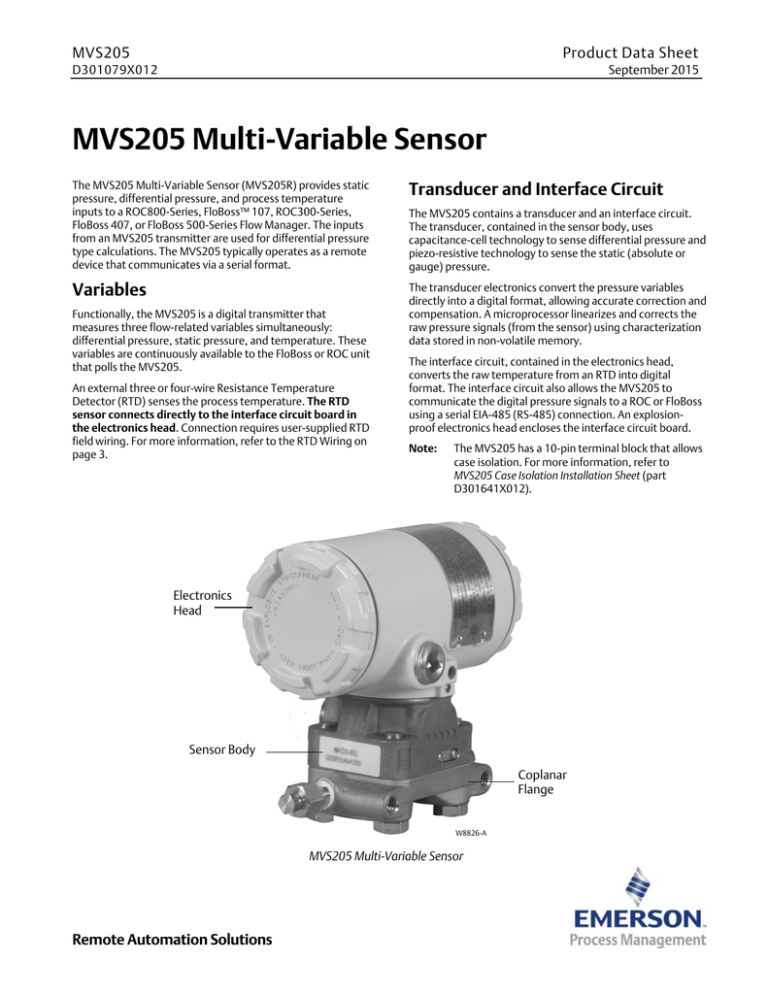
Electronics
Head
Sensor Body
Coplanar
Flange
W8826-A
MVS205 Multi-Variable Sensor
Remote Automation Solutions
MVS205
September 2015
Accuracy
Two versions of the pressure transducer used in the MVS205
transmitter are available:
205P with reference accuracy of 0.075% of the full span.
205E with reference accuracy of 0.10% of the full span.
Mounting
Attached to the bottom of the sensor body is a Coplanar™
flange. This flange, which provides drain and vent valves,
allows the MVS205 to mount on a pipestand, on a wall or
panel, or on an integral orifice assembly or manifold valve.
Note: CE marked assemblies come with cover clamps
installed on both ends of the MVS205 to comply
with ATEX and IECEx.
6.15
(156)
INCH
(mm)
2.81
(71)
4.73
(120)
MVS205aa.dsf
MVS205 Panel Mounting
S
LO
E
P
W
IVE
ATM
OS
ARNI NG
P
-
E
-
H
X
IN
RE
P
K E E
AL
I V E
-
-
H
I
I
T
T
G
T
W H
E N
R
CI
C
U
INCH
(mm)
INCH
(mm)
6.25
(159)
3.54
(90)
MVS205ac.dsf
MVS205a.dsf
MVS205 Pipe Mounting (Horizontal and Vertical Pipe)
2
www.EmersonProcess.com/Remote
MVS205
September 2015
MVS205 Multi-Variable Sensor
Terminations
Terminal
Description
1
Earth Case
1
EARTH DR
Earth Drain
COMM A
RX / TX +
COMM B
RX / TX —
RTD REF
RTD REF
RTD +
RTD +
EARTH CS
RTD —
RTD —
RTD RET
RTD RET
PWR +
Power —
PWR —
Power +
1. See part D301641X012 for
information on isolating the case
from power.
RTD Wiring
To connect a remote MVS205 to an RTD sensor assembly, install the sensor in the pipeline
and connect a RTD cable to the terminations on the interface board inside the remote MVS
sensor head. An armored cable requires no conduit to be used in a Class I, Division 2
hazardous non-incendiary area. In a Class I, Division 1 area, unarmored cable may be used if
installed in conduit that includes seals per hazardous installation practices.
Note: When installing an RTD in the field, any length/gauge combination of wire that adds
measurable resistance to the loop will cause a change in resistance that will affect the
RTD readings. It is recommended that end users calibrate or bias out the excess
resistance. To do this, perform a standard calibration at a process level (calibrate the
RTD input using the desired length of wire). Calibrating the input and not
compensating for the excess resistance caused by the length of the run will result in
inaccurate readings.
2-Wire
3-Wire
4-Wire
www.EmersonProcess.com/Remote
RTD REF
Jumper to RTD+
RTD +
Red with Jumper to RTD REF
RTD —
White
RTD RET
None
RTD REF
Red
RTD +
Red
RTD —
White
RTD RET
None
RTD REF
Red
RTD +
Red
RTD —
White with Jumper to RTD RET
RTD RET
White with Jumper to RTD —
3
MVS205
September 2015
Differential Pressure Input
Range1
0 to 62.2 kPa (0 to 250 InH2O)
0 to 248.8 kPa (0 to 1000 InH2O)
Reference Accuracy
205E (10:1 rangeability
allowed)
205P (100:1 rangeability
allowed)
Turndowns
from 1:1 to
10:1 of URL
0.10% of span
Turndowns
from 10:1 to
100:1 of URL
Not allowed
Turndowns
from 1:1 to
10:1 of URL
0.075% of span
Turndowns
from 10:1 to
100:1 of URL
[0.025 + 0.005(URL/Span)]% of span
Stability
0.125% of URL for five years, with up to 50°F (28°C) ambient temperature changes and up
to 1000 psi (68,9 bar) line pressure
Ambient Temperature Effect per
50°F (28°C)
Spans from 1:1 to 30:1
(0.025% URL + 0.125% of span)
Spans from 30:1 to 100:1
(0.035% URL + 0.175% of span)
Zero error
0.05% of URL per 1000 psi (68,9 bar)
Span error
0.20% of DP Reading per 1000 psi (68,9 bar)
Static Pressure Effects
Over-Pressure Limit
3,626 psi (250 bar) applied on either or both sides without damage to the sensor
Burst Pressure Limit
10,065 psi (694 bar)
1.
Consult factory for special ranges and materials which may be available. For example, 0 to 6.22 kPa (0 to 25 InH2O) at 0.10% reference
accuracy.
Static Pressure Input
Range
Either Absolute or Gauge:
0 to 5516 kPa (0 to 800 psia/psig)
0 to 25,000 kPa (0 to 3626 psia/psig)
Reference Accuracy
205E (10:1 rangeability
allowed)
205P (100:1 rangeability
allowed)
Stability
4
Turndowns
from 1:1 to
10:1 of URL
0.10% of span
Turndowns
from 10:1 to
100:1 of URL
Not allowed
Turndowns
from 1:1 to
10:1 of URL
0.075% of span
Turndowns
from 10:1 to
100:1 of URL
[0.03 + 0.0075(URL/Span)]% of span
0.125% of URL for five years, with up to 50°F (28°C) ambient temperature changes
www.EmersonProcess.com/Remote
MVS205
September 2015
Ambient Temperature Effect per
50°F (28°C)
Over-Pressure Limit
Spans from 1:1 to 30:1
(0.05% URL + 0.125% of span)
Spans from 30:1 to 100:1
(0.06% URL + 0.175% of span)
Same as URL
Process Temperature Input
Type
For 3- or 4-wire platinum 100-ohm RTD (conforming to IEC 751 Class B), with = 0.00385
Range
—40 to 400°C (—40 to 752°F)
Reference Accuracy
±0.28°C (±0.5°F), exclusive of RTD sensor and wiring errors (see Note under Terminations, RTD
Wiring).
Note:
Excitation Current
Includes linearity, hysteresis, and repeatability effects.
1.24 mA
Output
EIA-485 (RS-485)
Asynchronous serial communication using an MVS module-based proprietary
communications protocol for up to 1220 m (4000 ft) distance (wired in daisy-chain pattern
and properly terminated).
Power
Input at 0 to 75°C (32 to 167°F)
8 to 30 Vdc, 200 mW average
Input at —40 to 0°C (—40 to 32°F)
8.5 to 30 Vdc, 200 mW average
Isolation
The power input can optionally be isolated from the case, which may be grounded separately.
For further information, see MVS205 Case Isolation Installation Sheet (part D301641X012).
Physical
Dimensions
147 mm H by 163 mm W by 84 mm D (5.8 in. H by 6.4 in. W by 3.3 in. D)
Weight
3.0 kg (6.7 lb), including head
Vibration Effect
Sensor outputs shall not shift more than +0.1% of upper range limit per g from 5 to 2000 Hz in
any axis when tested per IEC 770, Section 6.2.14.
Construction
Standard
Transducer is all stainless steel construction with silicone fill fluid,
316L diaphragms and glass-filled PTFE o-rings. Electronics head is
A360 Aluminum with urethane coating.
Optional
Transducer includes Hastelloy C-276 wetted parts (construction is
NACE compliant per MR0103 and ISO15156/MR0175), inert fill
fluid
Pipestand
Mounts on 50 mm (2 in.) pipe with U-bolt and optional flange
bracket
Wall or Panel
Mounts with optional flange bracket, bolted on 71 mm (2.8 in.)
centers
Conduit
Head has two 1/2-inch NPT connections
Process
1/4-18 NPT on 2-1/8 inch centers (on coplanar flange)
Mounting
Connections
Environmental
Operating Temperature
—40 to 75°C (—40 to 167°F)
Storage Temperature
—50 to 100°C (—58 to 212°F)
www.EmersonProcess.com/Remote
5
MVS205
September 2015
Operating Humidity
0 to 99%, non-condensing
Process Seals per ANSI/ISA
12.27.01
Meets requirements for a Single Seal device as defined by ANSI/ISA 12.27.01. Installation must
adhere to the following process temperature limits.
Process Temperature (at
transmitter isolator flange)
Standard Silicone Fill
Sensor
—40 to 100°C (—40 to 212°F)
Inert Fill Sensor
—18 to 85°C (0 to 185°F)
Note: Process temperatures above 85°C (185°F) require you to lower the product’s
maximum ambient temperature rating by a 1.5:1 ratio. To determine the adjusted
maximum temperature rating, perform the following calculation:
Adjusted max Tamb = Product Max Tamb — [(Actual Process Tamb — 85°C (185°F)) * 1.5]
Example:
Adjusted Max Tamb = 75°C — [(95°C — 85°C) * 1.5] = 60°C.
Approvals
Product Markings for Hazardous
Locations
CSA C/US
Class I, Division 1, Groups C and D.
Class I, Division 2, Groups A, B, C, and D, T5 (Tamb=70°C [158°F]),
T4 (Tamb=75°C [167°F]).
Type 4X.
CE Marked
Ex d IIB T5 (Tamb=75°C)
Ex tD A21 IP66 T85°C
II 2 GD.
0081.
ATEX Cert. KEMA 04ATEX2182 X
IEC Cert. IECEx KEM 07.0055X
Approval Standards
6
TR CU 012/2011
Certified by NANIO “CCVE” RU C-US.ГБ05.B.01184 valid from 16.06.2015 to 16.06.2020
1Ex d IIB T5X
-40C0≤Ta≤+75C0
IP66 CSA/UL
CSA C22.2 No. 30
CSA C22.2 No. 213
UL 1203, UL 1604
ANSI/ISA 12.27.01-2003
EMC
EN 61000-4-2 (2001)
EN 61000-4-3 (2002)
EN 61000-4-4 (1995)
EN 61000-4-5 (2001)
EN 61000-4-6 (2003)
ATEX
EN 60079-0 (2006)
EN 60079-1 (2007)
EN 61241-0 (2004)
EN 61241-1 (2006)
IECEx
EN 60079—0 (2004 Edition 4)
EN 60079—1 (2007-04 Edition 6)
EN 61241—0 (2004 Edition 1)
EN 61241—1 (2004 Edition 1)
EN 60529 (2001)
www.EmersonProcess.com/Remote
MVS205
September 2015
Miscellaneous Approval
Certificates
Measurement (Industry)
Canada
Approved for use with approved flow computers. Approved as
MVS205R Series Remote Sensors (Measurement Canada approval
#AG-0412).
Canadian Registration to
Category ‘F’ Fittings
CRN 0F7768
Note:
Applies to all Canadian provinces and territories.
Customs Union
TR CU 004/2011, TR CU 020/2011
Certified by “Technoneftegaz”
TC RU C-US.HO03.B.00155 valid from 19.05.2015 to 18.05.2020
www.EmersonProcess.com/Remote
7
MVS205
September 2015
For customer service and technical support,
visit www.emersonprocess.com/remote/support
Headquarters:
Emerson Process Management
Remote Automation Solutions
6005 Rogerdale Road
Houston, TX 77072 U.S.A.
T +1 281 879 2699 | F +1 281 988 4445
www.EmersonProcess.com/Remote
Europe:
Emerson Process Management
Remote Automation Solutions
Unit 8, Waterfront Business Park
Dudley Road, Brierley Hill
Dudley UK DY5 1LX
T +44 1384 487200 | F +44 1384 487258
www.EmersonProcess.com/Remote
North American/Latin America:
Emerson Process Management
Remote Automation Solutions
6005 Rogerdale Road
Houston TX USA 77072
T +1 281 879 2699 | F +1 281 988 4445
www.EmersonProcess.com/Remote
Middle East/Africa:
Emerson Process Management
Remote Automation Solutions
Emerson FZE
P.O. Box 17033
Jebel Ali Free Zone — South 2
Dubai U.A.E.
T +971 4 8118100 | F +971 4 8865465
www.EmersonProcess.com/Remote
Asia-Pacific:
Emerson Process Management
Remote Automation Solutions
1 Pandan Crescent
Singapore 128461
T +65 6777 8211| F +65 6777 0947
www.EmersonProcess.com/Remote
Remote Automation Solutions
© 1995-2015 Remote Automation Solutions, a business unit of Emerson Process
Management. All rights reserved.
Remote Automation Solutions, a business unit of Emerson Process Management, shall not be
liable for technical or editorial errors in this manual or omissions from this manual. REMOTE
AUTOMATION SOLUTIONS MAKES NO WARRANTIES, EXPRESSED OR IMPLIED, INCLUDING THE
IMPLIED WARRANTIES OF MERCHANTABILITY AND FITNESS FOR A PARTICULAR PURPOSE WITH
RESPECT TO THIS MANUAL AND, IN NO EVENT SHALL REMOTE AUTOMATION SOLUTIONS BE
LIABLE FOR ANY INCIDENTAL, PUNITIVE, SPECIAL OR CONSEQUENTIAL DAMAGES INCLUDING,
BUT NOT LIMITED TO, LOSS OF PRODUCTION, LOSS OF PROFITS, LOSS OF REVENUE OR USE
AND COSTS INCURRED INCLUDING WITHOUT LIMITATION FOR CAPITAL, FUEL AND POWER,
AND CLAIMS OF THIRD PARTIES.
Emerson Process Management Ltd, Remote Automation Solutions (UK), is a wholly owned
subsidiary of Emerson Electric Co. doing business as Remote Automation Solutions, a business
unit of Emerson Process Management. FloBoss, ROCLINK, ControlWave, Helicoid, and
OpenEnterprise are trademarks of Remote Automation Solutions. AMS, PlantWeb, and the
PlantWeb logo are marks owned by one of the companies in the Emerson Process Management
business unit of Emerson Electric Co. Emerson Process Management, Emerson and the Emerson
logo are trademarks and service marks of the Emerson Electric Co. All other marks are property
of their respective owners.
The contents of this publication are presented for informational purposes only. While every
effort has been made to ensure informational accuracy, they are not to be construed as
warranties or guarantees, express or implied, regarding the products or services described
herein or their use or applicability. Remote Automation Solutions reserves the right to modify
or improve the designs or specifications of such products at any time without notice. All sales
are governed by Remote Automation Solutions’ terms and conditions which are available upon
request. Remote Automation Solutions does not assume responsibility for the selection, use or
maintenance of any product. Responsibility for proper selection, use and maintenance of any
Remote Automation Solutions product remains solely with the purchaser and end-user.


