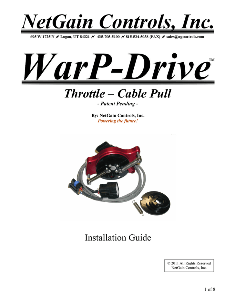
Throttle – Cable Pull
- Patent Pending By: NetGain Controls, Inc.
Powering the future!
Installation Guide
© 2011 All Rights Reserved
NetGain Controls, Inc.
1 of 8
Introduction
Thank you for purchasing a NetGain Controls WDT-CP Throttle Assembly. This device will allow you
to easily and reliably interface a cable-drive throttle pedal or level to this sensor for input to a
compatible piece of electronics. While designed to input to the WarP-Drive speed controllers, with some
modifications, it can be used with other pieces of equipment.
This throttle assembly device is built to last a lifetime. It has dual sealed bearings, a high quality
waterproof Hall-effect sensor, anodized aluminum base, and stainless steel hardware throughout. Its
patent-pending design has been intelligently thought out to provide the most versatile and reliable
operation possible.
This installation guide shows you how to connect and mount the throttle assembly. Installation is
straight-forward, and simple to perform. Follow the instructions in this guide and your throttle will be
interfaced quickly.
Installation Overview
Estimated time: 15-30 minutes to complete the installation.
1. Determine a suitable mounting point that is within reach of the existing throttle cable, and does
not interfere with any other components.
2. Mount the throttle assembly in the chosen location.
3. Determine the throttle cable travel distance from off to full on.
4. Select the closest inner disc matching the distance determined in the previous step.
5. Remove the inner disc that the unit shipped with.
6. Install the selected inner disc, route the throttle cable, and replace the top disc and springs.
7. Secure the throttle cable sheath mounting point.
8. Test the throttle pedal to ensure full travel is accomplished. Adjust as necessary.
9. Test the springs for proper operation and adjust as necessary.
Package Contents
When you open the package, verify that you received everything.
The package includes:
•
•
•
•
Throttle assembly with top disc, 1.5” disc, and springs installed.
Four additional discs, for 1.125”, 1.250”, 1.75”, and 2” travel.
One low tension spring.
Electrical cable assembly with connectors for the WDT-CP and a WarP-Drive controller.
2 of 8
Tools Required
The following tools might be required for the
installation:
•
•
•
2.5 Metric hex wrench
7mm socket and ratchet (or 7mm
combination wrench)
10mm socket and ratchet
Illustration 1: Possible tools required
for installation
Mounting
The throttle assembly can be mounted in several ways. The easiest is to find a flat ledge or overhang to
where the assembly can bolt flat. Standoffs can also be used to mount the assembly over a flat surface.
Use at a minimum two of the available mounting holes. Choose a location that suits the routing of the
throttle cable. The throttle cable must be able to reach the throttle assembly without causing excessive
bending or interference that would affect its smooth operation.
Illustration 2: Possible mounting position in a
vehicle, on the frame rails
Ensure that the throttle assembly has clearance around all moving parts so that nothing could potentially
interfere or bind the throttle assembly. This is CRITICAL to the safe operation of the device.
3 of 8
Determine Throttle Cable Travel
The throttle cable travel must be determined to properly configure the throttle assembly. This process
will likely require the assistance of a helper. Other methods than those suggested here might be
effectively used.
Position a ruler against the end of the throttle cable, keeping tension on the cable. Take note of where on
the ruler the throttle cable end is located. Have the helper fully depress the throttle pedal. Take note of
the new position that the throttle cable end is on the ruler. From these two points, determine the throttle
cable travel distance.
Illustration 3: Fully extended throttle
cable measurement
Illustration 4: Fully depressed throttle
cable measurement
The pictures above show the process of taking the measurements of the throttle cable travel. The first
measurement with the cable fully extended shows about 4 1/8”. The next picture with the throttle pedal
depressed shows about 2 1/4”. That leaves a distance of about 1 7/8”.
In some cases, the end stop of the throttle was provided by the original throttle body that the cable
connected to. In these situations, with the throttle cable disconnected from the original throttle body, a
longer travel might be measured than what the vehicle originally utilized. Where possible, it is helpful to
verify throttle cable travel measurements with the cable connected to the stock throttle body.
Install Throttle Cable
Remove the four bolts and lock-washers that retain the top disc. The bolts require a 2.5 metric hex
wrench. Also remove all four nuts on the spring-retaining studs. These require a 7mm socket or wrench.
Set these nuts, lockwashers, and bolts in a safe place where they will not be lost. Remove the top plastic
disc.
Inner discs are available in 1.125”, 1.25”, 1.5”, 1.75”, and 2”. Choose the disc that measures just less
than than the measurement taken in the previous step. For example, if the measurement was 1. 7/8” as
measured in the section above, use the 1.75” disc. Using a disc that larger than the measurement taken
will potentially result in less than 100% throttle being possible.
4 of 8
If the default shipped inner disc (usually 1.5”) is not the correct disc for your application, remove it and
then install the correct disc.
Position the throttle cable around the inner disc so that it will pull the throttle in the right direction. Place
the throttle cable barrel end into the hole corresponding with the installed inner disc. The throttle cable
assembly is designed to be compatible with most conventional throttle cable ends. If your throttle cable
does not have a barrel on the end, or the barrel is too large to fit in the hole, or the barrel is less
than 3/16” in diameter, use of the throttle assembly is not recommended. Use of the throttle under
any of these conditions is not supported unless prior approval is obtained in writing by NetGain
Controls. Any modifications to the throttle assembly will void the warranty.
Illustration 5: Throttle cable barrel installation
In the picture above, notice the direction that the cable exits. The cable exit point should be at least 90
degrees from the cable barrel to achieve linear behavior between the sensor rotation and cable travel.
Replace the top disc, ensuring that the cable barrel end is captive in the cable barrel holes in the top and
bottom discs. Install a M4 lock nut on each spring stud. Turn it down until contacts the top plastic disc.
Make sure it is tight against the disc and that both plastic discs are compressed together tightly. Be
careful to not overtighten the M4 lock nut as it could crack the plastic discs or loosen the stud.
Place each of the two springs over the spring studs. Install the M4 lock nut only on the lower tension
spring at this time. The nut for the other spring will be installed in a later step. The lock nut must be
installed inverted, that is, the side with the nylon lock-portion exposed is screwed on first. The nylon
lock portion is initially threaded from the factory to make this process easier, however, it can be a bit
challenging to get it to start. Make sure as it is tightened that it does not require excessive force. If it
binds, it is slightly off and needs to be backed off and restarted. Tighten the nut until it contacts the
bottom lock nut. Make sure the spring does not get caught between the two nuts. The spring should rest
on the rounded portion of the bottom nut. Again ensure that the spring is not pinched between the nuts,
but rather rests on the rounded portion of the bottom nut. It must rotate freely on the nut!
The next step involves mounting the cable sheathing end (usually a threaded portion of the cable sheath
that allows for adjustment). In some cases, it is possible to use the stock bracket that held this part of the
cable. In other cases, a custom bracket must be fabricated. Mount the bracket so that it rests in the
5 of 8
middle of the adjustment area (if the cable end has provision for adjustment). Mount it so the cable is
taut against the throttle assembly cam, but does not cause it to rotate. Depress the throttle pedal and
verify that the throttle assembly rotates and that all mounted components remain intact without flexing
or movement.
Electrical Connection
If the throttle is being used with a WarP-Drive controller, simply connect the provided cable with the
supplied connectors to the throttle assembly and the controller. If another controller or device is used
with the controller, determine the wiring order by comparing the electrical specifications of the throttle
(listed at the end of this document in the “Electrical Specifications”) with the requirements of your
device. Be careful to not apply a supply voltage greater than that listed in the throttle assembly
specifications and to not accidentally connect it with reverse polarity (ground and supply reversed).
NetGain Controls only recommends using a device that utilizes both throttle channels as opposed to only
a single channel. The installer is responsible for determining that the throttle meets applicable safety
requirements for the target installation.
Test and Adjust
With the throttle cable connected to the throttle assembly and the throttle cable sheathing end secured,
the installation is ready for testing and fine tuning. The testing procedure will depend on the particular
system that is reading the throttle signal. This manual will discuss the procedure for testing with a WarPDrive controller that has the Interface Module (IM) connected. Make sure that all testing is done with
the driven system in a state where motor operation is not possible!
While looking at the IM throttle reading, verify that with the throttle pedal not depressed, the throttle
reading is 0%. If the reading is anything other than 0%, use the adjustment of the throttle cable sheathing
end to let out some slack in the cable. Do this until the IM reads exactly 0%.
Now, completely depress the throttle pedal. Ensure that the IM reads 100%. If it doesn't reach the 100%
reading, the wrong inner disc was chosen. Return to the step of choosing the right inner disc, and repeat
the procedure from that point. If full throttle is reached substantially before the throttle is fully
depressed, it is likely that too small of an inner disc was chosen. Try the next size larger disc and repeat
the procedure from that point.
Spring Force Adjustment
Both springs are required for safe operation. Either spring must be capable on its own of returning the
throttle to zero in case the other spring breaks. The unit is shipped with a higher tension and a lower
tension spring. To this point, the top M4 lock nut on the higher tension spring has not been installed.
Remove the higher tension spring from the spring stud. With two people, have one person fully depress
the throttle and the other person watch the throttle assembly. Have the person depressing the throttle
quickly let off the pedal. The person watching the throttle assembly needs to ensure that the single lower
tension spring is capable of quickly snapping the throttle to 0%. If the throttle returns slowly, or does not
return, it must be determined what is causing the binding! The lower tension spring must be capable
6 of 8
of returning the throttle to zero on its own! Do no proceed until this has been verified.
Replace the higher tension spring onto the spring stud. Check the feel on the throttle pedal. It should be
comfortable to press. If it feels too heavy to press, replace the higher tension spring with the included
lower tension spring. Repeat the test to see if this provides comfortable operation.
If the throttle pedal is too easy to press with the lower tension and higher tension spring installed, a
second higher tension spring can be obtained from NetGain Controls to replace the lower tension spring.
This should not be necessary for most installations.
The top M6 lock nuts on the outer spring studs must be installed inverted as are the top M4 lock nuts on
the inner spring studs. Ensure that they are installed in this manner.
Once the springs have been tested for proper operation, install the other top M4 lock nut on the spring
stud in the same way the other one was installed. Verify that the lock nuts are installed properly with
the top lock nut inverted and the spring rotating freely on the rounded portion of both lock nuts!
Also make sure that the springs have clearance between the bolts that secure the top disc and that
nothing catches or binds! There must be no binding in the operation of the throttle assembly.
Everything must operate smoothly! Do not proceed until smooth, comfortable operation has been
verified!
Maintenance Procedures
It is recommended that the throttle unit is regularly checked for proper operation. However, if installed
correctly, no adjustment, lubricating, or maintenance is required.
Physical Specifications
Weight:
Dimensions:
Frequency Response:
Throttle Connector:
Controller Connector:
Operational Cycles:
1 lb, 3 oz
3” x 4.5” x 2.75”
1000 Hz minimum
METRI-Pack 150.2 series, p/n 12162260
Molex MX150L, p/n 19418-0022
35 million
Electrical Specifications
Input Voltage:
Input Current:
Orange wire:
Blue wire:
White wire:
Green wire:
Black wire:
Red wire:
Accuracy:
5.0VDC +/- 0.25VDC
10mA maximum per channel
Channel 1, 0.5V to 4.5V
Ground for channel 1
5V supply for channel 1
Channel 2, 0.25V to 2.25V
Ground for channel 2
5V supply for channel 2
+/- 2.0% of full scale for room temperature
7 of 8
+/- 3.0% of full scale over operating temperature range
Environmental Specifications
Electromagnetic compatibility:
Vibration:
Shock:
Operating temperature range:
Storage temperature:
Protection:
100V/meter, 14kHz – 1GHz range
10G peak, 20 – 2000 Hz
50Gs, half sine pulse, 5ms duration
-40C to 85C
-55C to 105C
Sensor sealed to IP66/IP67
8 of 8

