RA 29 864/06.98
RA
29 864/06.98
MDSD (Series 2X)
Mobile Dual Solenoid Driver
Replaces 11.97
The MDSD amplifier provides control of components that use
proportional solenoids without LVDTs for actuation. The MDSD
incorporates the following features:
– Wide supply voltage range: 10–28 VDC
– On board, replaceable fuse
– Reverse voltage protection
– Pulse Width Modulated (PWM) outputs
– PWM frequency adjustable from 75–275 Hz
– Max. and min. current separately adjustable for both
solenoids
– High current driver, regulated to within 1.0%, continuous
operation
– Infinite duration short circuit protection on both outputs
– Reference voltage provided for control via an external
potentiometer (>1K Ohm)
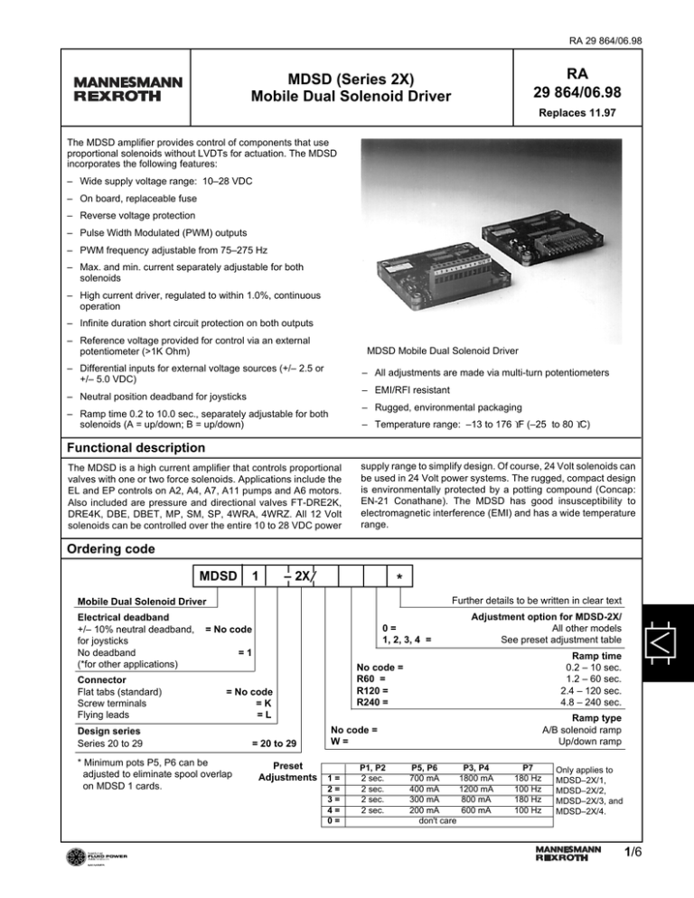
MDSD Mobile Dual Solenoid Driver
– Differential inputs for external voltage sources (+/– 2.5 or
+/– 5.0 VDC)
– All adjustments are made via multi-turn potentiometers
– EMI/RFI resistant
– Neutral position deadband for joysticks
– Rugged, environmental packaging
– Ramp time 0.2 to 10.0 sec., separately adjustable for both
solenoids (A = up/down; B = up/down)
– Temperature range: –13 to 176 °F (–25 to 80 °C)
Functional description
The MDSD is a high current amplifier that controls proportional
valves with one or two force solenoids. Applications include the
EL and EP controls on A2, A4, A7, A11 pumps and A6 motors.
Also included are pressure and directional valves FT-DRE2K,
DRE4K, DBE, DBET, MP, SM, SP, 4WRA, 4WRZ. All 12 Volt
solenoids can be controlled over the entire 10 to 28 VDC power
supply range to simplify design. Of course, 24 Volt solenoids can
be used in 24 Volt power systems. The rugged, compact design
is environmentally protected by a potting compound (Concap:
EN-21 Conathane). The MDSD has good insusceptibility to
electromagnetic interference (EMI) and has a wide temperature
range.
Ordering code
MDSD
1
– 2X
*
Further details to be written in clear text
Mobile Dual Solenoid Driver
Electrical deadband
+/– 10% neutral deadband,
for joysticks
No deadband
(*for other applications)
Connector
Flat tabs (standard)
Screw terminals
Flying leads
0=
1, 2, 3, 4 =
= No code
Adjustment option for MDSD-2X/
All other models
See preset adjustment table
=1
= No code
=K
=L
Design series
Series 20 to 29
* Minimum pots P5, P6 can be
adjusted to eliminate spool overlap
on MDSD 1 cards.
= 20 to 29
Preset
Adjustments
Ramp time
0.2 – 10 sec.
1.2 – 60 sec.
2.4 – 120 sec.
4.8 – 240 sec.
No code =
R60 =
R120 =
R240 =
Ramp type
A/B solenoid ramp
Up/down ramp
No code =
W=
1=
2=
3=
4=
0=
P1, P2
2 sec.
2 sec.
2 sec.
2 sec.
P5, P6
P3, P4
700 mA
1800 mA
400 mA
1200 mA
300 mA
800 mA
200 mA
600 mA
don't care
P7
180 Hz
100 Hz
180 Hz
100 Hz
Only applies to
MDSD–2X/1,
MDSD–2X/2,
MDSD–2X/3, and
MDSD–2X/4.
1/6
RA 29 864/06.98
Technical data (for operation outside these parameters, please consult us!)
Power supply voltage
VDC
Power requirement
VDC = 10 to 28
P = I2max • RSOL • 1.2
(Refer to valve or pump data sheet for max. solenoid current
and hot solenoid resistance)
W
Power supply current
Amp
Ramp time
sec.
Control potentiometer
Pulse frequency
P7
Fuse – 5x20 mm fast acting
I=
0.2 to 10 (standard)
1.2 to 60 (R60)
2.4 to 120 (R120)
4.8 to 240 (R240)
KΩ
1 to 10
Hz
75 to 275
Amp
4
°F (°C)
Ambient temperature
Weight
P
VDC
–13 to 176 (–25 to 80)
lbs
0.36
Terminal block connections
Potentiometer / joystick control
Terminal
Block
V+
I+
2
2
2
IA
1
VDC
2
GND
3
SOL A
4
GND
5
SOL B
6
GND
7
+5.1V
8
+2.55V
9
H+
10
L+
11
L-
12
H-
Power
Supply
A
7
A
B
A
(only)
1K
1K
1K
B
(only)
B
1K
A
8
IB
7
B
7
8
10
11
11
11
11
*
*
A (only)
*
A and B
B (only)
A and B
* Ground shield at one end only
9
9
9
External voltage commands:
4-20mA
10
±10V
+
10
200k
330
1/4W
11
12
12
±5.1V
+
±2.51V
+
10
11
12
*
*
A (only)
*
A and B
2/6
*
A and B
A and B
±2.5V use terminals 10 and 11,
V10 > V11 for Sol A
±5.0V use terminals 9 and 12,
V9 > V12 for Sol A
±10V use terminals 9 and 12,
add 200 KΩ resistor between
10 and 11, V9 > V12 for Sol A
Functional diagram MDSD
Unidirectional
inc
cw
A-max
P3
A-time
(up/down)
P1
L+
H+
100K
50K
9
100K
+5.1 V
7
VDC
1
B-max
P4
P2
B-time
(up/down)
Step Generator
V
5
6
B
W-Ramp
4A
Regulator
a
b
t
inc
cw
GND
PWM Voltage
to Current
Summation
B-min
P6
Power
Supply
A
P7
Unidirectional
inc
cw
8
t
inc time
cw
50K
+2.55 V
Frequency
a
b
100K
4
P5
inc time
cw
Ramp
11
10
3
inc
cw
±5.0 V ±2.5 V
L-
100K
12
A-min
inc
cw
H-
Step Generator
inc
cw
Differential
Input
PWM Voltage
Summation to Current
V
inc
cw
2
P1
P2
(Up)
(Down)
A/B-time A/B-time
RA 29 864/06.98
3/6
RA 29 864/06.98
Output curves
MDSD Solenoid A
Output Current (Amps)
3
2.5
Extended Range
by increased
“min.” current
2
1.5
P3
1
Adjustment Range
0.5
P5{
0
MDSD Dual Solenoid
0.10A
10
20
30
40 50 60 70
Input Voltage (%)
80
90
100
Sol A
Sol B
Output Current (Amps)
3
Adjustment Range
P4
Adjustment Range
P5{
0
0.10A
}P6
1
2
Extended Range
3
100 80 60 40 20
20 40
0
Input Voltage (%)
Output Current (Amps)
Sol A
P3
1
MDSD – 1 Dual Solenoid
Sol B
Extended Range
2
60
80
100
3
Extended Range
2
P3
1
Adjustment Range
P4
Adjustment Range
P5{
0
0.10A
}P6
1
2
Extended Range
3
0
100 80 60 40 20
20 40
Input Voltage (%)
60
80
100
Potentiometer Adjustments
4/6
P1
Ramp time (std.)
Sol A
P2
Ramp time (std.)
SolB
P3
Max. current
Sol A
P4
Max. current
SolB
P5
Min. current
Sol A
P6
Min. current
SolB
P7
PWM frequency
0.2
10 sec.
0
2.5 A
0.1
2.5 A
75
275 Hz
RA 29 864/06.98
Unit dimensions: dimensions in inches (millimeters)
MDSD…K; Screw Terminals
3.41
(86.7)
2.85
(72.4)
ø 0.150 (3.8) holes
(4 places)
1 2 3 4 5 6 7 8 9 101112
3.60
(91.4)
4.20
(107)
P2 P1
J3
J1
J2
P7
P4 P3 P6 P5
Screw terminals
12 AWG (2.5 mm2)
1.49
(37.8)
Encapsulated
MDSD…; Flat Tabs
3.41
(86.7)
2.85
(72.4)
1 2 3 4 5 6 7 8 9 101112
3.60
(91.4)
Typical terminal types
Tab per DIN 46249
4.20
(107)
P2 P1
0.197 typ.
(5)
P4 P3 P6 P5
1.25
(31.8)
ø 0.150 (3.8) holes
(4 places)
J3
Mates with 0.25 in. and 0.11 in.
female tab connectors
J1
J2
P7
Encapsulated
(1 - 2)
(3 - 12)
5/6
RA 29 864/06.98
Unit dimensions: dimensions in inches (millimeters)
MDSD…L; Flying Leads
Lead length
Approx.
6.0
(150)
3.41
(86.7)
2.85
(72.4)
ø 0.150 (3.8) holes
(4 places)
1 2 3 4 5 6 7 8 9 101112
3.60
(91.4)
4.20
(107)
P2 P1
P4 P3 P6 P5
J3
J1
J2
P7
Encapsulated
Approx.
0.8
(20)
Drawing not to scale
Board
1
2
3
4
5
6
7
8
9
10
11
12
Wire Color
Red
Black
Blue
White/Blue
Brown
White/Brown
Yellow
Orange
Violet
Gray
White/Gray
White/Violet
Leads are 18 AWG stranded
UL style 1429 or equivalent,
Irradiated PVC
Mannesmann Rexroth Corporation
Rexroth Hydraulics Div., Industrial, 2315 City Line Road, Bethlehem, PA 18017-2131 Tel. (610) 694-8300 Fax: (610) 694-8467
Rexroth Hydraulics Div., Mobile, 1700 Old Mansfield Road, Wooster, OH 44691-0394 Tel. (330) 263-3400 Fax: (330) 263-3333
6/6
All rights reserved – Subject to revision
Printed in U.S.A.


