Catalogue
advertisement

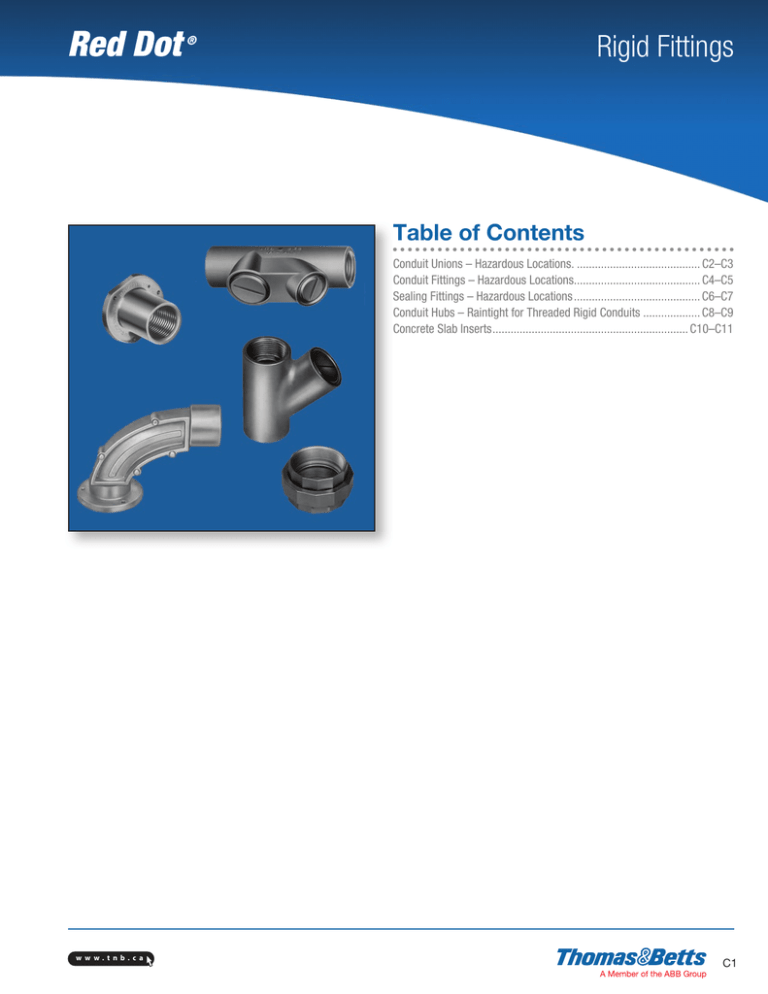
Red Dot Rigid Fittings ® Table of Contents Conduit Unions – Hazardous Locations........................................... C2–C3 Conduit Fittings – Hazardous Locations.......................................... C4–C5 Sealing Fittings – Hazardous Locations........................................... C6–C7 Conduit Hubs – Raintight for Threaded Rigid Conduits.................... C8–C9 Concrete Slab Inserts.................................................................. C10–C11 w w w. t nb. c a C1 Red Dot Rigid Fittings ® Conduit Unions – Hazardous Locations Applications •Unions are used as connecting elements between enclosures, fittings or boxes which permitfuture changes to the system in both hazardous and non-hazardous areas. Features/Benefits •Copper-free (less than .004 copper content) aluminum provides increased corrosion resistance • Precision cast and machined surfaces permit safer wire pulling • Precision NPT threaded hubs allow trouble-free field installation for rigid or IMC conduit • Clear UL, CSA and cubic content markings speed approval by inspectors • Unique concentric ring design insures critical flame path control Standard Materials • Die cast aluminum alloy A360 (less than 0.004 copper content) • EXMU nipples are galvanized steel Standard Finish • Aluminum lacquer finish Compliances Compliances as noted on each page of the catalogue include: • CSA Certified • UL Listed •Class I, Div. 1 and 2, Groups C, D – Explosionproof Class II,Div. 1, Groups E, F, G – Dust-Ignitionproof Class III, Div. 1 and 2 – Raintight NEMA 3, 4, 7 CD, 9 EFG – Wet Locations Smooth conduit stops Precision machined threads Unique concentric ring design Copper-free aluminum (less than 0.004 copper content) C2 w w w.t nb.c a Red Dot Rigid Fittings ® Conduit Unions – Hazardous Locations Male and Female Conduit Unions Cat. No. Hub Size (in.) Female to Female Union (Cast Aluminum) 1/2 EXFU-1 3/4 EXFU-2 1 EXFU-3 1-1/4 EXFU-4 1-1/2 EXFU-5 2 EXFU-6 2-1/2 EXFU-7 3 EXFU-8 3-1/2 EXFU-9 4 EXFU-10 A (in.) B (in.) C (in.) 1-3/4 1-9/32 1-15/16 2 1-19/32 2-3/16 1-7/8 2-3/4 2-1/4 3-3/16 2-5/32 3 2-21/32 3-1/2 3-3/16 4-1/4 3-1/4 3-15/16 5 3-1/2 4-17/32 5-5/8 3-5/8 5-1/8 6-9/32 w w w. t nb. c a Hub Size (in.) A (in.) B (in.) C (in.) Female to Female Union (Cast Aluminum) 1/2 EXMU-1 1-3/4 3/4 EXMU-2 1 2 EXMU-3 1-9/32 1-15/16 1-19/32 2-3/16 Cat. No. D (in.) 2-15/32 2-9/16 2-11/16 C3 Red Dot Rigid Fittings ® Conduit Unions – Hazardous Locations Applications • Junction for branch conduits • Accessible wiring chamber provides a convenient location to pull conductors Features/Benefits • Copper-free (less than .004 copper content) aluminum provides increased corrosion resistance • Precision cast and machined surfaces permit safer wire pulling • Precision NPT threaded hubs allow trouble-free field installation for rigid or IMC conduit • Deep slotted cover screws for faster installation • Clear UL, CSA and cubic content markings speed approval by inspectors Standard Materials • Die cast aluminum alloy A360 (less than 0.004 copper content) Standard Finish • Aluminum lacquer finish Compliances Compliances as noted on each page of the catalogue include: • CSA Certified • UL Listed •Class I, Div. 1 and 2, Groups C, D – Explosionproof Class II,Div. 1, Groups E, F, G – Dust-Ignitionproof Class III, Div. 1 and 2 – Raintight NEMA 3, 4, 7 CD, 9 EFG – Wet Locations Precision machined threads and surfaces Heavy wall construction Deep slotted screws Smooth conduit stops Copper-free aluminum (less than 0.004 copper content) C4 w w w.t nb.c a Red Dot Rigid Fittings ® Conduit Unions – Hazardous Locations Conduit Elbows and Capped Elbows Hub Size (in.) A (in.) B (in.) C (in.) “LB” Style Conduit Body (Cast Aluminum) 1/2 4-3/16 EXLB-1 EXLB-2 3/4 4-5/8 EXLB-3 1 5-3/8 3-1/4 3-5/8 4-1/2 1-3/4 1-15/16 2-5/16 Cat. No. D (in.) 1-9/32 2-1/32 E (in.) 1-11/16 1-13/16 2-3/16 Hub Size (in.) A (in.) B (in.) C (in.) D (in.) E (in.) F (in.) “T” Style Conduit (Cast Aluminum) 1/2 4-1/4 EXLB-1 EXLB-2 3/4 4-3/4 EXLB-3 1 5-1/2 1-3/8 1-1/2 1-7/8 2-1/8 2-3/8 2-11/16 1/2 9/16 7/16 1-11/16 1-13/16 2-3/16 1-1/16 1-1/32 7/16 Cat. No. Cat. No. Hub Size (in.) A (in.) Capped Elbow Female to Female (Cast Aluminum) 1/2 1-13/16 GYF-1 GYF-2 3/4 2-9/32 GYF-3 1 w w w. t nb. c a B (in.) C (in.) 1-1/8 2 1-9/16 2-7/16 C5 Red Dot Rigid Fittings ® Sealing Fittings – Hazardous Locations Applications: • Limits flames and/or explosions to area within electrical system where they originate • Limits pressure piling •Required for conduit systems in hazardous locations 18 in. from an enclosure housing a heat producing or arcing device; on 2 in. and larger system which enters an enclosure containing splices; wherever conduit leaves a Class I, Division I area and enters a non-hazardous area Features/Benefits: • Copper-free (less than 0.004 copper content) aluminum provides increased corrosion resistance • Precision cast and machined surfaces permit safer wire pulling • Precision NPT threaded hubs allow trouble-free field installation for rigid or IMC conduit •Large opening provides maximum working room for creating dam and seal pouring to speed up installation • Compact design permits close construction of parallel conduit runs Standard Materials: • Sealing Fittings: Die cast aluminum alloy A360 (less than 0.004 copper content) • Sealing Cement • Fiber: Flame retardant Kaowool Type A fiber Standard Finish: • Aluminum lacquer finish Compliances: Compliances as noted on each page of the catalogue include: • CSA Certified • UL Listed •Class I, Div. 1 and 2, Groups C, D – Explosionproof Class II,Div. 1, Groups E, F, G – Dust-Ignitionproof Class III, Div. 1 and 2 – Raintight NEMA 3, 4, 7 CD, 9 EFG – Wet Locations Smooth Copper-free aluminum (less than 0.004 copper content) conduit stops Large aperture for easy installation Precision machined threads C6 w w w.t nb.c a Red Dot Rigid Fittings ® Sealing Fittings – Hazardous Locations Cat. No. Hub Size (in.) Cement Qty Vertical Sealing Fittings (Cast Aluminum) 1/2 EYVF-1* 3/4 EYVF-2* – 1 EYVF-3* 1/2 2 oz. EYVF-11ф 3/4 3 oz. EYVF-22ф 1 4 oz. EYVF-33ф Fiber Qty A (in.) B (in.) – 2-3/4 2-7/8 3-7/16 1-3/16 1-3/8 1-5/8 1/32 oz. 1/16 oz. 1/8 oz. 2-3/4 2-7/8 3-7/16 1-3/16 1-3/8 1-5/8 1-9/16 1/2 2-13/16 3-5/16 A (in.) B (in.) C (in.) D (in.) 4-1/32 4-3/32 4-3/8 1-5/32 1-3/8 13-9/64 1-1/64 1-7/8 2-3/32 2-5/16 5 2-1/16 2-7/16 2-15/16 1-1/8 2-7/8 3-1/4 3-3/4 C (in.) 1-5/16 1-9/16 1-5/16 D (in.) 1/2 2-13/16 3-5/16 * Packaged with an adequate amount of sealing compound close-up plugs installed. ф Approximate amount of cement and fiber required in oz. per hub EVHF-4 through 6 EVHF-1 through 3 Cat. No. Hub Size (in.) Cement Qty Fiber Qty Vertical / Horizontal Sealing (Cast Aluminum) 1/2 2 oz. EVHF-1ф 1/32 oz. 3/4 3 oz. EVHF-2ф 1 4 oz. EVHF-3ф 1/4 oz. ф 1/2 4 oz. EVHF-4 3/4 6 oz. 1/2 oz. EVHF-5ф 1 12 oz. 1 oz. EVHF-6ф ф Approximate amount of cement and fiber required in oz. per hub Cat. No. Quantity Sealing Cement 3.2 oz. EXSC-2 13 oz. EXSC-8 1 lb, 10 oz. EXSC-16 w w w. t nb. c a Volume (Cu. in.) 2 oz. 3 oz. 4 oz. Cat. No. Packing Fiber EXPF-16† † Quantity 1 lb CSA not applicable C7 Red Dot Rigid Fittings ® Conduit Hubs – Raintight for Threaded Rigid Metal Conduits Applications: • A fitting for connecting junction box to junction box, or junction box to the conduit system. The resulting connection maintaining ground continuity is raintight. • Suitable for use where the system is normally hosed down (NEMA 4) for cleaning Features/Benefits: • Plastic insulated throat, precision cast and machined surfaces permit safer wire pulling • Special flush locking nipple design provides maximum space for wiring in the box • Captive O-Ring fits snugly in groove preventing loss and fumbling with parts •Knurled inner face of locking nipple provides 360 degrees of locking and bites through box paint to ensure grounding •Locking nipple has tightening lugs on two planes for easier assembly in hard to reach field conditions •Grounding hubs have a ground screw located within the enclosure providing a tamper-proof ground for device • Locking nipple design permits replacement of the box without disassembling the installation Standard Materials: • HTZ Series: Certified die cast zinc alloy ZAMAK 3 • HT Series: Die cast aluminum alloy A360 (less than 0.004 copper content) Standard Finish: • Aluminum lacquer finish Compliances: Compliances as noted on each page of the catalogue include: • CSA Certified • UL Listed •Class I, Div. 1 and 2, Groups C, D – Explosionproof Class II,Div. 1, Groups E, F, G – Dust-Ignitionproof Class III, Div. 1 and 2 – Raintight NEMA 3, 4, 7 CD, 9 EFG – Wet Locations Smooth conduit stops Plastic insulated throat Knurled teeth bite box Captive O-ring Convenient ground screw option C8 Precision machined threads Space saving design w w w.t nb.c a Red Dot Rigid Fittings ® Conduit Hubs – Raintight for Threaded Rigid Metal Conduits Mntg. Hole (Thread) NPT Cat. No. Hub Size (in.) A (in.) B (in.) 1-3/8 C (in.) D (in.) Panel Thickness E (in.) F (in.) G (in.) Min. G (in.) Max. J (in.) O-Ring Size 55/64 1-3/32 1-5/16 1-43/64 1-29/32 2-3/8 2-7/8 3-1/2 4 4-1/2 59/64 1-11/64 1-27/64 1-51/64 2-13/64 2-21/32 3-5/32 3-49/64 4-7/16 4-63/64 214 218 222 225 227 231 236 241 245 248 G (in.) Min. G (in.) Max. J (in.) O-Ring Size 55/64 1-3/32 1-5/16 1-43/64 1-29/32 2-3/8 2-7/8 3-1/2 59/64 1-11/64 1-27/64 1-51/64 2-13/64 2-21/32 3-5/32 3-49/64 214 218 222 225 227 231 236 241 G (in.) Min. G (in.) Max. J (in.) O-Ring Size 55/64 1-3/32 1-5/16 1-43/64 1-29/32 2-3/8 2-7/8 3-1/2 4 4-1/2 59/64 1-11/64 1-27/64 1-51/64 2-13/64 2-21/32 3-5/32 3-49/64 4-7/16 4-63/64 214 218 222 225 227 231 236 241 245 248 Insulated Throat (Cast Zinc) HTZ1 HTZ2 HTZ3 HTZ4 HTZ5 HTZ6 HTZ7 HTZ8 HTZ9 HTZ10 1/2 3/4 1 1-1/4 1-1/2 2 2-1/2 3 3-1/2 4 1-19/32 1-23/32 1-3/4 1-25/32 2-1/4 2-21/64 2-23/64 2-3/8 1-13/32 1-21/32 1-7/8 2-5/16 2-5/8 3-5/32 2-45/64 4-5/16 4-13/16 5-5/16 Hub Size (in.) A (in.) B (in.) 3/16 1/4 1/4 3/8 1/2 – 14 3/4 – 14 1 – 11-1/2 1-1/4, 11-1/2 1-1/2, 11-1/2 2 – 11-1/2 2-1/2, 8 3–8 3-1/2, 8 4–8 60 45 Cat. No. C (in.) D (in.) Panel Thickness E (in.) F (in.) Insulated Throat and Ground Screw (Cast Zinc) HTGZ1 HTGZ2 HTGZ3 HTGZ4 HTGZ5 HTGZ6 HTGZ7 HTGZ8 1/2 3/4 1 1-1/4 1-1/2 2 2-1/2 3 1-3/8 1-19/32 1-23/32 1-3/4 1-25/32 2-1/4 2-21/64 1-13/32 1-21/32 1-7/8 2-5/16 2-5/8 3-5/32 2-45/64 4-5/16 Hub Size (in.) A (in.) B (in.) 3/16 1/4 1/4 3/8 1/2 – 14 3/4 – 14 1 – 11-1/2 1-1/4, 11-1/2 1-1/2, 11-1/2 2 – 11-1/2 2-1/2, 8 3–8 60 45 Cat. No. C (in.) D (in.) Panel Thickness E (in.) F (in.) Insulated Throat (Cast Aluminum) HT1 HT2 HT3 HT4 HT5 HT6 HT7 HT8 HT9 HT10 w w w. t nb. c a 1/2 3/4 1 1-1/4 1-1/2 2 2-1/2 3 3-1/2 4 1-3/8 1-19/32 1-23/32 1-3/4 1-25/32 2-1/4 2-21/64 2-23/64 2-3/8 1-13/32 1-21/32 1-7/8 2-5/16 2-5/8 3-5/32 2-45/64 4-5/16 4-13/16 5-5/16 3/16 1/4 1/4 3/8 1/2 – 14 3/4 – 14 1 – 11-1/2 1-1/4, 11-1/2 1-1/2, 11-1/2 2 – 11-1/2 2-1/2, 8 3–8 3-1/2, 8 4–8 60 45 C9 Red Dot Rigid Fittings ® Concrete Slab Inserts Applications: • Permits in-slab ceiling drops and floor mounts in poured concrete • Provides flush threaded conduit hub for mounting, pulling and future access to conduit systems • Design permits prefabrication of in-slab conduit system Features/Benefits: • Flush design leaves no broken or bent stubs for easy removal of undamaged forms • Flush design permits simplified in-slab work • Flush design leaves a neat, uncluttered job •Offered in straight ES configuration for straight through conduit runs and mounting of floor boxes in slabs over 6 in. thick • Offered in ESL configuration to eliminate bending of conduit in slabs over 4 in. thick • Precision cast and machined surfaces permit safer wire pulling • ZAMAK 3 Zinc can be embedded in concrete Standard Materials: • Die cast zinc alloy ZAMAK 3. Certified by the Certified Zinc Alloy Plan (CZAP) Standard Finish: •Natural Compliances: Compliances as noted on each page of the catalogue include: • CSA Certified • UL Listed Old Way Conduit running in a cement slab is bent 90º to run through a hole drilled in the form. Drilling takes time and damages the form. Stripping form often damages conduit stubs. Varying length of stubs requires individual measuring and cutting of conduit drops. Red Dot Way Conduit running in a cement slab is attached to a 90º concrete slab insert, or conduit is bent 90º and is threaded to a straight insert. Nail or screw fitting to wood or metal forms. After concrete is poured and forms stripped, conduit drops quickly into fittings. Drops are easily measured from ceiling line to switch or outlet height and cut in uniform lengths. 4" Slab ESL 6" Slab ES C10 w w w.t nb.c a Red Dot Rigid Fittings ® Concrete Slab Inserts Concrete Tight Conduit Inserts Cat. No. Hub Size (in.) Straight Conduit Inserts (Zinc) 1/2 ES-1 3/4 ES-2 1 ES-3 A (in.) B (in.) C (in.) D (in.) 1-1/32 1-59/64 1-9/16 1-23/32 2-11/64 1-5/8 1-31/32 1-1/4 2-9/16 2 2-5/16 1-17/32 E (in.) 1/4 Cat. No. Hub Size (in.) A (in.) 90º Angle Conduit Inserts (Zinc) 1/2 4-27/32 ESL-1 3/4 5-11/64 ESL-2 1 5-5/32 ESL-3 w w w. t nb. c a B (in.) C (in.) D (in.) E (in.) F (in.) 1-1/32 3-45/64 3-29/32 3-3/16 1-7/8 3-23/32 4-1/8 4-1/8 2-1/8 1-1/4 3-3/4 3-15/16 3-15/16 2-7/16 1-17/32 G (in.) 1/4 C11 Red Dot C12 ® w w w.t nb.c a


