R
E
T
E
S T
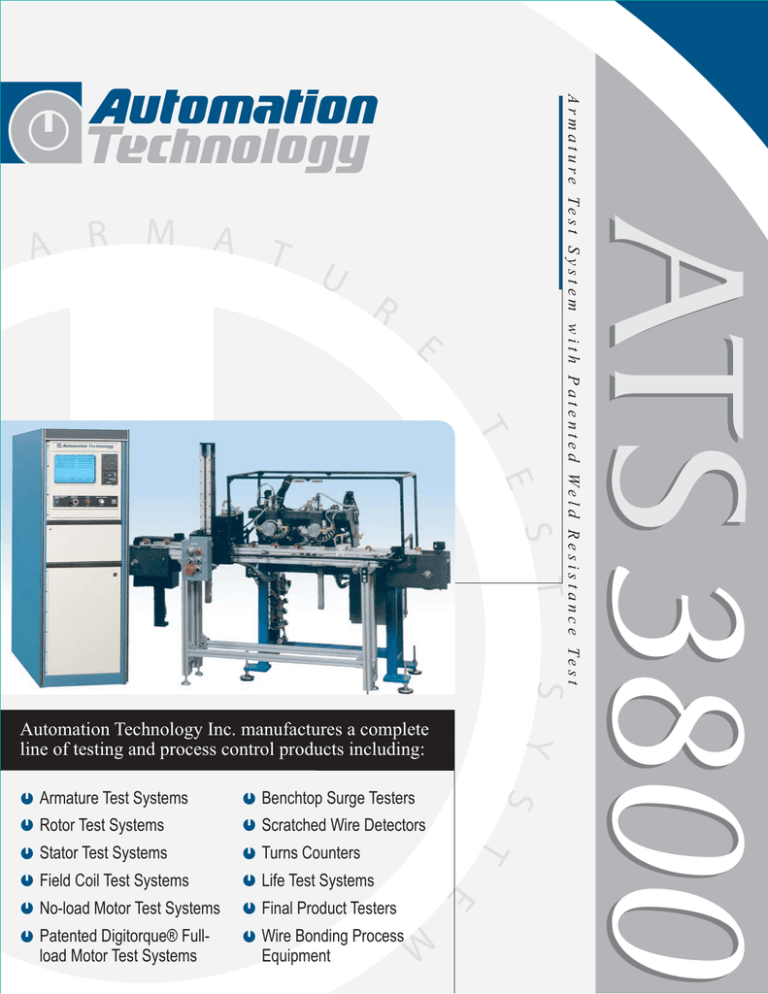
ATS 3800
U
S
Y
S
Automation Technology Inc. manufactures a complete
line of testing and process control products including:
Benchtop Surge Testers
Rotor Test Systems
Scratched Wire Detectors
Stator Test Systems
Turns Counters
Field Coil Test Systems
Life Test Systems
No-load Motor Test Systems
Final Product Testers
Patented Digitorque® Fullload Motor Test Systems
Wire Bonding Process
Equipment
T
Armature Test Systems
A r m a t u r e Te s t S y s t e m w i t h P a t e n t e d We l d R e s i s t a n c e Te s t
A R M A T
E
M
summary
of
tests
per formed
HIP OT /DI E L ECTRI C
ATI utilizes the latest concepts in Hipot/Dielectric testing.
Important Standard features incorporated in this test include:
Capacitance Compensation separates the real resistive
current from the sometimes very large capacitive current
which flows as a result of winding to core capacitance. This
feature permits maximum leakage current limits to be set
lower and provides better analysis of the Stator insulation.
Ramped Turn-on of Hipot Voltage eliminates the high
current inrush associated with the instantaneous application of high voltage to the part under test. If a ground
is detected during the voltage ramp-up, Hipot power is
removed before damage can occur.
True RMS Measurement of both leakage current and
applied voltage is more accurate due to the requirement
to measure parameters that contain out-of-phase
components.
Arc Detection is a feature that detects arcing that is
sometimes observed at the peaks of the test voltage.
This arcing, because of the short duration, may not
be of sufficient magnitude to cause the RMS leakage
current to exceed the maximum leakage current limit.
Independent Modular Test Shelves allow for simple
calibration and quick diagnostics
ATI also offers bench-top Hipot testers from
manufactures such as Quadtech that may be
incorporated as an option to our standard Hipot test.
RESISTA N CE
To provide the greatest possible accuracy, ATI’s Armature Test System utilizes a number of technical features when
performing a resistance test that are not common in competitor’s equipment. Following are some of these features:
Test current is kept to a minimum and applied for the
facilities is at harmonics of the power line frequency.
shortest amount of time possible to avoid heating of the
This is a feature not found in competitor’s products.
copper or aluminum magnet wire. Because magnet wire
A sixteen-bit converter is used for the A to D
has a resistance temperature coefficient of approximately
measurement. Typical competitive Systems are twelve-bit.
0.4 %/°C, it is important to avoid heating the wire in order
Ambient temperature compensation is standard. Optional,
to produce stable, repeatable measurement values.
non-contact, infrared, part temperature measurement is
Connection to the Armature commutator bars
available. This temperature compensation feature normalis made via a 4-wire Kelvin connection.
izes the resistance measurements back to programmable
Both test current and the resultant voltage drop
standard laboratory conditions typically 25°C.
are integrated over one line cycle and measured
simultaneously. This integration over a power line cycle
The combination of the above features and test methods
causes the voltage and current values to be extensively
provide the best Gage R&R of any Armature Test
filtered at harmonics of the line frequency. Most
System available (particularly at the very low
electrical noise found in motor manufacturing
resistance ranges below 0.100 Ohms).
S U R G E
( I M P U L S E )
The surge test is conducted by discharging a charged high voltage capacitor into the coil under test. The result
is a decaying ringing pulse at a frequency defined as f=1/(2π LC). Measurement of the surge data is as follows:
ATI’s high-resolution timer circuitry measures the period
variables, ATI has developed a method whereby the ratios
of this frequency to a resolution of 20 nanoseconds.
of the period measurements within an armature are
(0.00000002 seconds). Typical period readings would be
compared to programmable ratio limits. This permits the
in the range of 50.00 µS to 250.00 µS. Extremely small
setting of very tight ratio limits which detects very minor
changes in inductance such as shorted turns, incorrect
winding defects without having nuisance rejects resulting
turns count and incorrect turns placement can be easily
from variations in the steel, stach length, etc. Techniques
detected with this method. This type of test unlike most
used in competitive equipment do not permit this
others is not affected by small variations in test voltage.
capability.
To avoid nuisance rejects caused by inductance or
capacitance variations resulting from acceptable process
W E L D
R E S I S TA N C E
For armatures having Tang (hook) type commutator
connections, ATI's Weld Resistance Test tests the connections
of the armature commutator connections and the resistance
values of the individual windings using a pair of independent
constant current sources connected across opposite pairs of
armature windings throught their respective commutator bars.
The constant current sources are identical in output current
and are connected in opposite polarity to minimize circulating
Test Summary/Operator Screen: This screen displays
the model being tested in each fixture, the sequence
number and the result of each test performed.
current from flowing in other windings of the armature. The
voltages developed across windings adjacent the two current
cources are combined and are a function of the resistances of
the connections between the windings and the commutator
bars. The voltages across each constant current source
represent the resistance of the winding to which it is
connected.
Fixture Detail Screen: There are one of these screens
per fixture that can be selected. These screens display
actual numerical measured data for each test being
conducted at the selected fixture.
manual
or automated
fixturing
ATI offers a complete range of system configurations
from manual to fully automatic lines. Systems can be
integrated into new or existing manufacturing lines. Test
heads utilize gold plated, pogo pins to make a reliable
Kelvin connection to the commutator bars. For manual
systems, safety interlocked light curtains are used
whenever possible to speed load/unload time providing
maximum throughput.
For high production systems, ATI testers utilize a test
head like that shown. These heads have two
independent connections (Kelvin) at each commutator
bar. The connections are made using easily replaceable,
gold-plated, pogo pins. The test head's cam design
allows all connections to be engaged/disengaged using a
single air cylinder. The cam design means that ALL
connections are either engaged or disengaged.
The Patented Lift and Slide system for automatic lines
eliminates the load/unload time from the total cycle time
allowing true 100% utilization of the test system.
standard
& optional
features
S TA N D A R D F E AT U R E S :
Industry Leading Two-year Limited Warranty
Requires Only 120V AC Single Phase Power Input
Automatic Setting of HiPot and Surge Test Voltage
Easy to Use Windows® Operating System
Ambient Temperature Compensation
Results Management (Statistical Analysis)
Comprehensive Diagnostics Utilities
Inkjet Data Printer
Dual Hard Drives with Automatic File Backup Software
MagMap® and Digitorque® are registered
trademarks of Automation Technology Inc. Dayton,
Ohio
To align the Armature for Test in an Automatic Line Test
System, ATI incorporates our Patented method using nonmagnetic, wear resistant ceramic rollers. Because these
rollers are non-magnetic, they do not influence the Surge Test
Data by changing the capacitance of the armature under test.
ATI's Rotary Armature Test Fixture is ideal for lower volume
runs of varying configurations. This system allows testing of
armatures having varying numbers of bars, commutator
diamters, stack diameters, shaft diameters and lengths, etc.
Modem and Software to Provide Remote Diagnostics
Power Regulation and Power Transient Protection
Learn Mode with Percentage or Standard Deviation
Tolerances and Adjustable Thresholds for Resistance and
Surge
Capable of Network Interface
Simultaneous Testing on Dual Fixtures for Maximum
Throughput
O P T I O N A L F E AT U R E S :
Reject label Printer
Bar Code Reader
Touch Screen
Infrared Temperature Compensation
Automatic Passed Part Marker
Neutral Zone/Bar Advance Test
1900 Troy St. Dayton, Ohio 45404
Ph: 937.233.6084 Fax: 937.233.7813
e-mail: ati@atidayton.com
© 2001 Automation Technology Inc.
All rights reserved.
Dayton, Ohio
internet: http://www.atidayton.com
For technical assistance or ordering
information, please contact:

