Shut off Valve, In-line flange mounting, Model : SLBF-JRef. No : H04238, Release Oct 2006
* -2.0
the right connection
(Dimensions in mm)
Description
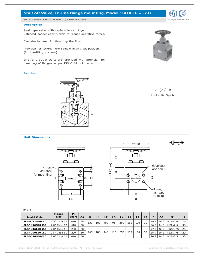
Seat type valve with replacable cartridge.
Balanced poppet construction to reduce operating forces.
Can also be used for throttling the flow.
Provision for locking
the spindle in any set position.
(for throttling purpose).
Inlet and outlet ports are provided with provision for
mounting of flanges as per ISO 6162 bolt pattern.
Section
A
B
Hydraulic Symbol
A
B
Unit Dimensions
B
l2
A
GG
for mounting
ØA (max)
at A and B
L3
l3
4 nos,
Ø18 thru
L2 (max)
L1
Ø190
l1
Q
L4
B
4 nos,
M1' tap,
t1 deep
Table 1
Model Code
Flange
Size
Pr
(bar)
ØA
SLBF-J12S40-2.0
1.5" Code 62
410
38
SLBF-J16S40-2.0
2.0" Code 62
410
50
SLBF-J16L50-2.0
2.0" Code 61
200
50
SLBF-J20L50-2.0
2.5" Code 61
200
60
SLBF-J16S50-2.0
2.0" Code 62
410
50
Copyrights© 2006
hyloc hydrotechnic pvt. ltd.
B
L1
L2
L3
L4
l1
l2
l3
135
183
408
95
200
160
120
35
145
188
All rights reserved
448
115
250
190
160
30
Q
GG
M1
t1
79.3
36.5
M16x2.0
26
96.8
44.5
M20x2.5
33
77.8
42.9
M12x1.75
20
88.9
50.8
M12x1.75
20
96.8
44.5
M20x2.5
33
Engineering Datasheet, Page 1/2
Shut off Valve, In-line flange mounting, Model : SLBF-JRef. No : H04238, Release Oct 2006
*-2.0
(Dimensions in mm)
the right connection
Technical Specifications
Construction
○
○
Mounting type
○
○
○
○
○
○
○
○
○
○
○
○
○
○
○
○
○
○
○
○
○
○
○
○
○
○
○
○
○
○
○
○
○
○
○
○
○
Seat type valve with seals on poppet. Partially balanced.
In line flange mounting, interface conforms to
ISO 6162 bolt pattern.
(ISO 6164 bolt pattern flanges are also available on request)
Mounting position
Flow direction
○
○
○
○
○
○
○
Operating pressure
Hydraulic medium
Viscosity range
○
○
○
○
○
○
○
○
○
○
○
○
○
○
○
○
○
○
○
○
○
Fluid cleanliness requirement
○
○
○
○
○
Maximum flow handling capacity
○
○
○
○
○
○
○
○
○
○
Optional
From port `A' to port `B'.
○
○
○
○
○
Refer Table 1
○
○
○
○
Mineral oil.
○
○
○
10 cSt to 380 cSt.
○
○
○
-20 oC to +70 oC.
○
○
○
As per ISO 19/16 or better.
○
○
Refer graph.
○
○
○
○
○
○
○
○
○
○
○
○
○
○
○
○
○
○
○
○
○
○
○
○
○
○
○
○
○
○
○
○
○
○
○
○
○
○
○
○
○
○
○
○
○
○
○
○
○
○
○
○
○
○
○
○
○
Fluid temperature range
○
○
Expected Performance Curves
Pressure drop in bar
10
8
NG - 40
6
4
NG - 50
2
0
0
200
400
600
800
1000
Flow in lpm
Ordering Code
SLB
F
J
12
Shut off Valve,
Slip in cartridge
(Balanced Piston)
L
40
2.0
Design Series
Subject to revision
Material
Omit
Steel
End Connection details
Flanged - F
Mounting Flange Standard
ISO 6162 - J
Flange Size
316
SS 316
Seals
Omit
Nitrile
V
FKM
Size (Valve)
1.1/2” - 12
40 - NG 40
2.0” - 16
50 - NG 50
2.1/2” - 20
Pressure series
L - Std Pressure
S - High Pressure
Copyrights© 2006
hyloc hydrotechnic pvt. ltd.
All rights reserved
Engineering Datasheet, Page 2/2

