Tweeter T35, T35B, T350
advertisement
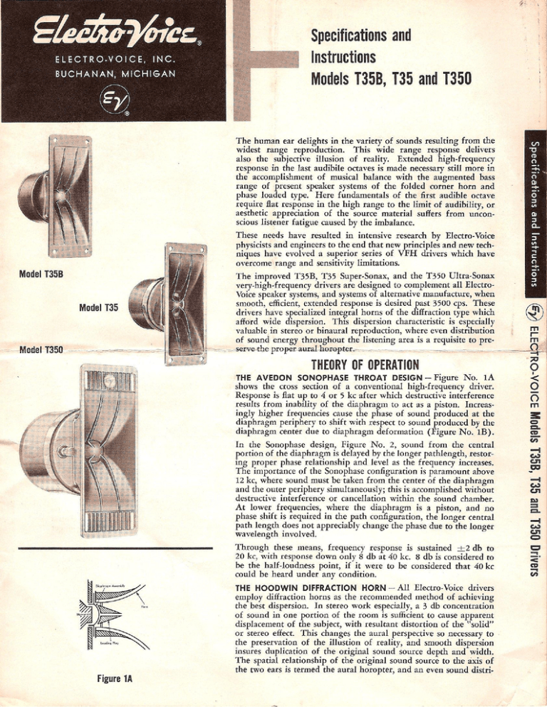
Specifications and ELECTRO-VOICE, INC. BUCHANAN, MICHIGAN Instructions Models T35B, T35 and T350 These needs have resulted i n intensive research by Electro-Voice physicists and engineers to the end that new principles and new techniques have evolved a superior series of V F H drivers which have overcome range and sensitivity limitations. Model T35B Model T35 =5 ss THEORY OF OPERATION THE AVEDON SONOPHASE THROAT DESIGN - Figure No. 1A I n the Sonophase design, Figure N o . 2, sound from the central portion of the diaphragm is delayed by the longer pathlength, restoring proper phase relationship and level as the frequency increases. The importance of the Sonophase configuration is paramount above 12 kc, where sound must be taken from the center of the diaphragm and the outer periphery simultaneously; this is accomplished without destructive interference or cancellation within the sound chamber. A t lower frequencies, where the diaphragm is a piston, and no phase shift is required in the path configuration, the longer central path length does not appreciably change the phase due to the longer wavelength involved. Through these means, frequency response is sustained ± 2 db to 20 kc, with response down only 8 db at 40 kc. 8 db is considered to be the half-loudness point, i f i t were to be considered that 40 kc could be heard under any condition. THE HOODWIN DIFFRACTION HORN - A l l Electro-Voice drivers employ diffraction horns as the recommended method of achieving the best dispersion. I n stereo work especially, a 3 db concentration of sound i n one portion of the room is sufficient to cause apparent displacement of the subject, with resultant distortion of the "solid" or stereo effect. This changes the aural perspective so necessary to the preservation of the illustion of reality, and smooth dispersion insures duplication of the original sound source depth and width. The spatial relationship of the original sound source to the axis of the two ears is termed the aural horopter, and an even sound distri- Figure 1A Models T35B, T35 and T350 Drivers shows the cross section of a conventional high-frequency driver. Response is flat up to 4 or 5 kc after which destructive interference results from inability of the diaphragm to act as a piston. Increasingly higher frequencies cause the phase of sound produced at the diaphragm periphery to shift with respect to sound produced by the diaphragm center due to diaphragm deformation (Figure N o . I B ) . ELECJTRO-VOICE Mode! T350 The improved T35B, T35 Super-Sonax, and the T350 Ultra-Sonax very-high-frequency drivers are designed to complement all ElectroVoice speaker systems, and systems of alternative manufacture, when smooth, efficient, extended response is desired past 3500 cps. These drivers have specialized integral horns of the diffraction type which afford wide dispersion. This dispersion characteristic is especially valuable in stereo or binaural reproduction, where even distribution of sound energy throughout the listening area is a requisite to preserve the proper^ aural h o r o p t e t ^ - ^ - ^ - ^ — — — -— = — = _ • Specifications and Instructions The human ear delights i n the variety of sounds resulting from the widest range reproduction. This wide range response delivers also the subjective illusion of reality. Extended high-frequency response in the last audibile octaves is made necessary still more i n the accomplishment of musical balance with the augmented bass range of present speaker systems of the folded corner horn and phase loaded type. Here fundamentals of the first audible octave require flat response in the high range to the limit of audibility, or aesthetic appreciation of the source material suffers from unconscious listener fatigue caused by the imbalance. bution, coupled with balancing the levels of both right and left speakers is insured through the diffraction principle. The Hoodwin diffraction principle is best illustrated by reference to the figures. Action o f d i a p h r a g m a t higher frequencies. line shows departure f r o m piston action. Figure 1B Sonophaie Assembly Loading Plug Diaphragm Voice Coil -"„.,...„.„„.,H Figure 2 Dotted FIGURE 3A — This shows how sound disperses equally i n all directions from a single point source. FIGURE 3B — I n this figure two sound sources are shown. On the axis, at point " x " , double the sound power results as the resultant pressures are in phase. FIGURE 3C — But i n this figure, i f the "distance between the two sources is V2 wavelength or greater, the sound from the two sources w i l l be considerably out of phase for points off the axis resulting in decreased sound pressure. FIGURE 3D — This figure will show the deficiencies i n horns of wide lateral dimensions compared to the wavelength being emitted. Any horn mouth can be considered as a group of small point sources of sound. They must beam the sound down the axis by their very nature. FIGURE 3E — I n this figure are shown representative horns, illustrating that horns must have a certain length, as well as cross sectional area along this length and at the mouth to load the driver diaphragm down to the lowest frequencies to be reproduced. The lower we go, the longer must be the horn and the greater the mouth area. This physical fact shows that large horn mouths necessarily beam the high frequencies. FIGURE 3F — This figure shows that narrowing the horizontal area and extending the vertical dimension of the horn mouth preserves the loading area necessary for good low end response, disperses the sound perfectly i n the horizontal direction where i t is so necessary, and keeps interfering reflections off the floor and ceiling. Figure 3A Figure 3B Corollary advantages of Hoodwin diffraction are much greater efficiency due to elimination of the viscous resistivity of the air caused by a multiplicity of horn throats, as i n cellular horns; elimination of losses due to friction caused by lens assemblies, and the obvious compactness of diffraction horns when contrasted to other media. VOICE COIL ASSEMBLY — B y using a diaphragm assembly of practically indestructible phenolic-impregnated linen, radial splitting, buzzing and modular breakup are eliminated. Because reproduction of the extreme high frequencies is mass-controlled, the self-supporting voice coil has no heavy coil form and is therefore practically weightless, providing extended high-frequency response. SPECIFICATIONS T35 T35B T350 Frequency Response: ± 2 d b 3.5 kc t o l 9 k c ± 2 d b 3.5kctol8kc ± 2 d b 3.5 kc to 21 kc Recommended Crossover: 3500 cps 3500 cps 3500 cps RETMA Sensitivity Rating: 57 d b 54 d b 60 d b Polar Pattern: 180° dispersion 180° dispersion 180° dispersion Program Material 50 warts 50 watts 50 watts Peak 100 watts 100 watts 100 watts Nominal Impedance: 16 ohms 16 ohms 16 ohms Voice Coil Diameter: 1 inch 1 inch 1 inch Magnet Weight: 7oz 4 oz 1 lb Gauss 13,500 9000 20,000 Horn 5Vt i n . long x 2 in. wide 514 i n . long x 2 in. wide 7V4 in. long x 2% in. wide Pot Diameter 214 i n . maximum 214 i n . maximum 3V4 i n . maximum Depth 314 i n . overall 3 in. overall 414 i n . maximum Mounting: See diagrams See diagrams See diagrams Baffle Opening: VA"X4VA" Wx414" 4%"x2%" . Net Weight: 214 lbs. 2 lbs. 7 lbs. Shipping Weight: 3*4 lbs. 3 lbs. 9'/2 lbs. Price: N e t $35.00 $22.00 Recommended Accessories: X36 crossover network, Pri e, Net: 9.50. Power Handling Capacity: Figure 3C Size: Figure 3D $60.00 AT37 leve control, Price, Net: $3.90
