GS-X v.III Guarding Safety Controller
Hold-to-Run Switch
Packaging
1 ea. 47-142117-000 Pkg. Hold-to-Run Cable Assembly
*1 ea. 47-142118-000 Pkg. Hold-to-Run Switch
1 ea. 47-902601-000 Installation Instructions
* One per Center Item
Tools Required
- Straight (flat) Screw Driver
- Phillips (cross) Screw Driver
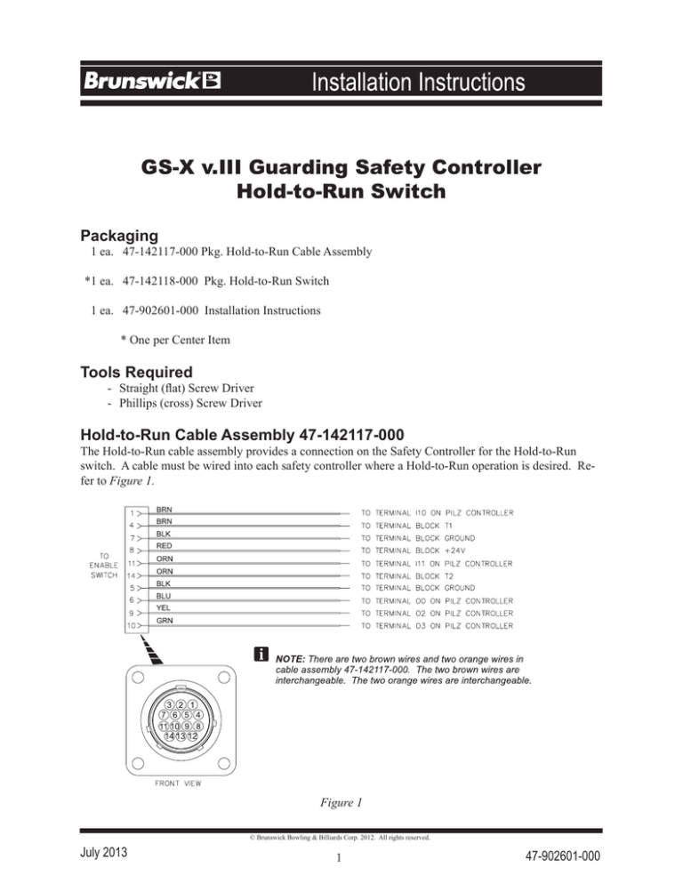
Hold-to-Run Cable Assembly 47-142117-000
The Hold-to-Run cable assembly provides a connection on the Safety Controller for the Hold-to-Run
switch. A cable must be wired into each safety controller where a Hold-to-Run operation is desired. Refer to Figure 1.
Figure 1
© Brunswick Bowling & Billiards Corp. 2012. All rights reserved.
July 2013
1
47-902601-000
Hold-to-Run Cable Installation in the Safety Controller
WARNING! Turn off the main power to the pinsetter at the main electrical panel
and turn “OFF” the main power switch on the safety controller.
1. Remove and discard cover plate from safety controller and retain all screws for re-use. Refer to
Figure 2.
Figure 2
IMPORTANT!: Save all screws.
2. Remove the cover from the safety controller.
WARNING! Verify all lights inside the safety controller are off before continuing.
2
3. Install hold-to-run cable assembly into safety controller with the 4 screws from step 1. Refer to
Figure 3.
Figure 3
3
4. Wire the hold-to-run cable assembly to safety controller. Refer to Figure 4 and Schematic of
Hold-to-Run Cable Figure 1.
NOTE: The existing orange wire connecting terminal Ill to terminal block T2 must be removed in
order for the hold-to run switch to function.
Figure 4
5. Secure the cover removed in step 4 to the safety controller.
4
Hold-to-Run Switch 47-142118-000
The Hold-to-Run switch is a manually operated switch that allows work to be conducted in the GS-X
pinsetter areas while the machine is operating. Refer to Figures 5 & 6.
Figure 5
Figure 6
NOTE: When the Hold-to-Run switch is not in use, remove it from the safety controller and store in
a secure location.
5
The Hold-to-Run switch has three positions that provide three operating modes. Refer to Figure 7.
Figure 7
6
Functional Test of the Hold-to-Run Switch
WARNING! The effectiveness of the Hold-to-Run switch must be tested before
use. Occupy a safe area, outside of the GS-X pinsetter and away from any
dangerous parts or areas that could cause injury.
1. With the hold-to-run switch connected to the safety controller (refer to page 4, Figure 6) in position 1 state (off, push button not pressed, GS-X pinsetter not operating), check all the protective
devices, interlocks and sensors before any work or the dangerous state of the pinsetter is initiated.
a. Completely cover each light beam with a test piece that is not transparent (at least 30 mm [1-3/16”] diameter) at the following positions:
- Directly in front of the sender
- In the middle between sender and receiver
- Directly in front of the receiver
b. Open the rear pinsetter access door with the interlock switch.
c. Open the masking unit interlock switch.
d. Press the emergency stop button.
Each of the preceding individual tests must produce the following result:
- During the light beam test the receiver for the related safety photoelectric safety switch must
have no LED illuminated. - As long as the light beam, interlock or emergency stop switch is interrupted, it must not be
possible to initiate the dangerous state of the pinsetter.
2. Operate the hold-to-run switch and verify all three positions (refer to page 5, Figure 7) operate
correctly while the GS-X pinsetter is in the dangerous state:
Position 1 - Off, push button not pressed, GS-X pinsetter not operating
Position 2 - Enabled, push button pressed to center position, GS-X pinsetter operational
Position 3 - Disabled, push button pressed to full down position, GS-X pinsetter not operating
3. Operate the hold-to-run switch in the position 2 state (enabled, push button pressed to center position) and verify all the interlocks and sensors will NOT disable the dangerous state of the pinsetter:
a. Completely cover each light beam with a test piece that is not transparent (at least 30 mm [1-3/16”] diameter) at the following positions:
- Directly in front of the sender
- In the middle between sender and receiver
- Directly in front of the receiver
b. Open the rear pinsetter access door with the interlock switch.
c. Open the masking unit interlock switch.
d. Press the emergency stop button.
During each of these tests the pinsetter should stay operational in the dangerous state WHILE the hold-torun switch is in the position 2 state (enabled, push button pressed to center position).
7

