Performance Improvement of Resonant Inductive Coupling for
advertisement

Performance Improvement of Resonant Inductive Coupling
for Wireless 3D IC Interconnect
Sangwook Han* and David D. Wentzloff
EECS Department, The University of Michigan, Ann Arbor, MI, USA
E-mail: {swhanpns, wentzlof}@umich.edu
Introduction
As the demands on high performance and multi-function systems increase, System-inPackage (SIP) provides a method for increasing integration with a reasonable cost and
short development time. SIP using vertically stacked (3D) ICs has the advantages of a
small form-factor and short communication distance between chips, leading to increased
data rate and efficiency. Several wired and wireless approaches for interconnect between
3D ICs have been proposed. Among them, wireless interconnect using inductive-coupling
is very promising since it has achieved low power, high performance with small size, and
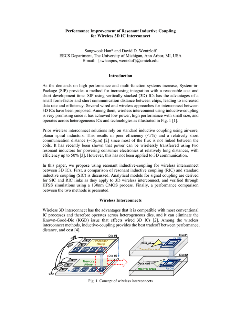
operates across heterogeneous ICs and technologies as illustrated in Fig. 1 [1].
Prior wireless interconnect solutions rely on standard inductive coupling using air-core,
planar spiral inductors. This results in poor efficiency (<5%) and a relatively short
communication distance (~15μm) [2] since most of the flux is not linked between the
coils. It has recently been shown that power can be wirelessly transferred using two
resonant inductors for powering consumer electronics at relatively long distances, with
efficiency up to 50% [3]. However, this has not been applied to 3D communication.
In this paper, we propose using resonant inductive-coupling for wireless interconnect
between 3D ICs. First, a comparison of resonant inductive coupling (RIC) and standard
inductive coupling (SIC) is discussed. Analytical models for signal coupling are derived
for SIC and RIC links as they apply to 3D wireless interconnect, and verified through
HFSS simulations using a 130nm CMOS process. Finally, a performance comparison
between the two methods is presented.
Wireless Interconnects
Wireless 3D interconnect has the advantages that it is compatible with most conventional
IC processes and therefore operates across heterogeneous dies, and it can eliminate the
Known-Good-Die (KGD) issue that effects wired 3D ICs [2]. Among the wireless
interconnect methods, inductive-coupling provides the best tradeoff between performance,
distance, and cost [4].
Fig. 1. Concept of wireless interconnects
A transmit-receive pair is illustrated in Fig. 1. Because the flux density, and therefore
signal strength, in inductive links is directly proportional to current in the transmitting
coil, the transmitter circuits should maximize current. On the receiver side, an amplifier
optimized for low noise figure and power presents a high-impedance load on the receiver
coil, therefore received voltage should ideally be maximized. SIC links operate well
below the self-resonant frequency of the inductors, therefore the parasitic capacitances
can be ignored and the SIC link is modeled as an equivalent circuit in Fig. 2(a).
and
model the losses in the coils. The transmitter is modeled as a current source operating
at a fixed frequency. The receiver is modeled as a large resister RL. The received voltage
VR for the SIC link is given by Eq. (1)
=
_
(1)
where k is the transformer coupling coefficient, L1 and L2 are the self-inductances of the
transmitter and receiver coils, respectively. Since the transmitter and receiver coils are
typically identical for SIC and RIC links,
. is the transmitter current
amplitude. The value of is found from simulations, and is a strong function of the
separation between coils
distance ), therefore its value determines the
communication distance.
The RIC circuit is shown in Fig. 2(b). External capacitors and have been added to
create resonant tanks at the transmitter and receiver sides. The resonant frequency can be
tuned by adjusting the capacitor values. RIC links operate in two regimes, depending on
the values of k and quality factor (
/ ), where is the loss in the inductor; the
strongly coupled regime (kQ ≥ 0.1) and the weakly coupled regime (kQ < 0.1). The link
characteristics are different in each regime, as discussed in the following two sections.
Fig. 2. (a) SIC equivalent circuit and (b) RIC equivalent circuit
Resonant Inductive Coupling in the Strongly Coupled Regime
The strongly-coupled regime is defined by kQ 0.1, that is, when the coils are close
together. In this regime, the coupling is strong enough that the loading on the receiver
side effects the resonant frequency at the transmitter side when reflected through the
transformer, and vice versa. This creates two resonant frequencies for the stronglycoupled RIC system, given by:
_
1/
1/
where
frequency, the received voltage
√
,
_
√
(2)
is the unloaded resonant frequency. At each resonant
for RIC with strong coupling is given by:
_
_
_
_
(3)
_
(4)
_
When k approaches 1, the advantage of RIC over SIC (Eq. 1) is an increase in received
voltage by a factor of approximately 2 . As the coil separation increases, reduces, and
and
converge on a single resonant frequency
. The RIC link then
_
_
transitions from strongly-coupled into the weakly-coupled regime as described below.
Resonant Inductive Coupling in the Weakly Coupled Regime
The weakly-coupled regime is defined by kQ < 0.1, that is, when the coils are far apart. In
this regime, the receiver load reflected to the transmitter side is negligibly small so that it
has no impact on the transmitter circuit. Therefore, the system has one resonance
1/
1/
. At , the receiver voltage
is given by Eq. (5).
frequency
(5)
_
In this regime, RIC significantly improves the received signal amplitude over SIC (Eq. 1)
by a factor of Q2 , which is typically much greater than 1.
Simulations
To verify these models, we designed planar spiral coils for SIC and RIC using a
Chartered 130nm CMOS process (Fig. 3). Two identical coils are vertically stacked to
simulate communicating through stacked ICs. The distance between them is swept from
5μm to 95μm, and HFSS is used to extract the lumped-element models for the coils.
These models are imported into Spectre to simulate the received voltage for a given
transmitter current excitation. The results are shown in Fig. 4. The nominal value of Q is
3.1, and the boundary of the weakly/strongly coupled regimes is k = 0.03. In the weakly
coupled regime, the RIC link has one resonant frequency, but as k increases, the
and
(Fig. 4(a)). Fig. 4(b) shows _ , _
at
frequency splits into
_
_
, and the ratio of the two. RIC improves the coupling over SIC by a factor of 10
_
(≈Q2) in the weakly-coupled, and 5~10 (≈2Q) in the strongly-coupled regimes. As k
is
increases, the stronger coupling increases _ . However, the ratio _ / _
decreasing, approaching 2 for
1, and also with reducing as frequency _
decreases.
TABLE I
DETAILS OF COILS
Fig. 3. HFSS coils design
Parameter
diameter
Width
space
Number of turns
Number of layers
L
C
R
Value
30μm
0.65μm
0.35μm
5
4
22nH
40fF
240Ω
Distance [um]
90
60
30
10
5
Calculated
Simulated (Lumped)
Simulated (HFSS)
1k
RIC (cal)
RIC (sim)
RIC (HFSS)
SIC (cal)
SIC (sim)
SIC (HFSS)
15
12
9
100
VR/IT [V/A]
VR_RIC/VR_SIC ratio
freq [GHz]
8
6
4
1m
10m
k
100m
3
10
Strongly
Coupled
Weakly
Coupled
6
RIC/SIC
ratio
1
1m
(a)
10m
k 100m
1
0
(b)
Fig. 4. (a) Resonant frequency depending on k and (b) received voltage depending on k
Conclusion
The performance of inductive links for 3D wireless interconnects in a package can be
improved by using resonant inductive coupling over standard inductive coupling.
Without increasing the size of the coils or power consumption, RIC can increase the
received voltage by factors of Q2 (weakly coupled) and 2Q (strongly coupled) compared
to SIC. The improvement of RIC is the highest in the weakly-coupled regime when the
received signal is smallest. Therefore, RIC can be exploited for small k to increase the
communication distance and separation between coils, enabling communication through
thicker die or multiple die, as well as wireless testing and verification.
References
[1] K. Niitsu et al, “An Inductive-Coupling Link for 3D Integration of a 90nm CMOS
Processor and a 65nm CMOS SRAM”, ISSCC Dig. Tech. Papers, pp. 480-481, Feb
2009.
[2] N. Miura et al, “A 0.14 pJ/b Inductive-Coupling Transceiver With DigitallyControlled Precise Pulse Shaping”, IEEE Journal of Solid-State Circuits, Vol. 43,
No.1, Jan. 2008.
[3] A. Kurs et al, “Wireless Power Transfer via Strongly Coupled Magnetic Resonances”,
Science Vol. 317, 83, 2007.
[4] Qun Gu et al, “Two 10Gb/s/pin Low-Power Interconnect Methods for 3D ICs”,
ISSCC Dig. Tech. Papers, pp. 448-449, Feb 2007.

