Application Note
Magnetic Position Sensing in Brushless DC Electric Motors
1.0INTRODUCTION
This application note discusses regulating the electronic
commutation in brushless DC electric motors (BLDC) with
the following Honeywell Hall-effect sensor ICs in place of the
mechanical commutation used in conventional brush-type DC
motors:
• Enhanced digital bipolar (SS30, SS31x/SS41x Series)
• Latching (SS36x/SS46x Series, VF360NT, VF360ST, VF460S)
BLDC motor technology, coupled with Honeywell’s Hall-effect
sensor ICs, provides a cost-effective and reliable alternative
to conventional DC motor commutation. Manufacturing and
operating cost savings can be realized in several areas:
• Honeywell Hall-effect sensor ICs are relatively low-cost
devices
• The low operate and release Gauss levels (at 25 °C ±40 °C)
allow the manufacturer to install lower-cost commutation
magnetics
• These solid-state sensor ICs have no moving parts to wear
out, eliminating maintenance and performance problems
created by brush wear and the associated dust.
2.0OVERVIEW
Brushless DC motors differ from brush-type DC motors in that
they employ electronic (rather than mechanical) commutation of
the windings.
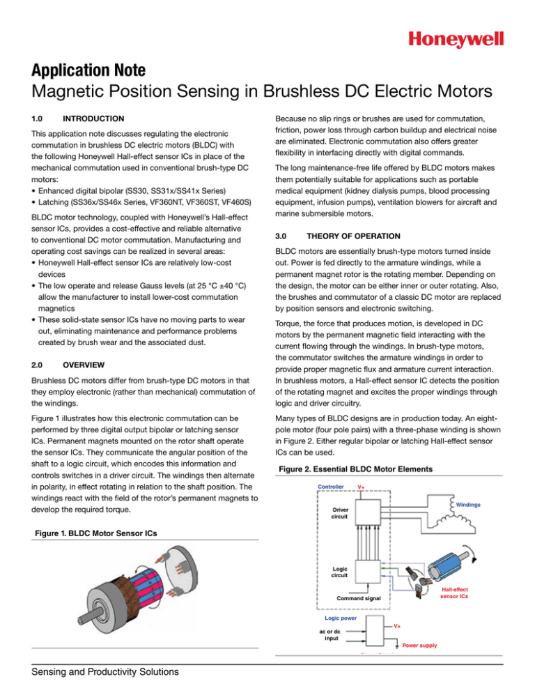
Figure 1 illustrates how this electronic commutation can be
performed by three digital output bipolar or latching sensor
ICs. Permanent magnets mounted on the rotor shaft operate
the sensor ICs. They communicate the angular position of the
shaft to a logic circuit, which encodes this information and
controls switches in a driver circuit. The windings then alternate
in polarity, in effect rotating in relation to the shaft position. The
windings react with the field of the rotor’s permanent magnets to
develop the required torque.
Because no slip rings or brushes are used for commutation,
friction, power loss through carbon buildup and electrical noise
are eliminated. Electronic commutation also offers greater
flexibility in interfacing directly with digital commands.
The long maintenance-free life offered by BLDC motors makes
them potentially suitable for applications such as portable
medical equipment (kidney dialysis pumps, blood processing
equipment, infusion pumps), ventilation blowers for aircraft and
marine submersible motors.
3.0
THEORY OF OPERATION
BLDC motors are essentially brush-type motors turned inside
out. Power is fed directly to the armature windings, while a
permanent magnet rotor is the rotating member. Depending on
the design, the motor can be either inner or outer rotating. Also,
the brushes and commutator of a classic DC motor are replaced
by position sensors and electronic switching.
Torque, the force that produces motion, is developed in DC
motors by the permanent magnetic field interacting with the
current flowing through the windings. In brush-type motors,
the commutator switches the armature windings in order to
provide proper magnetic flux and armature current interaction.
In brushless motors, a Hall-effect sensor IC detects the position
of the rotating magnet and excites the proper windings through
logic and driver circuitry.
Many types of BLDC designs are in production today. An eightpole motor (four pole pairs) with a three-phase winding is shown
in Figure 2. Either regular bipolar or latching Hall-effect sensor
ICs can be used.
Figure 2. Essential BLDC Motor Elements
Controller
V+
Windings
Driver
circuit
Figure 1. BLDC Motor Sensor ICs
Logic
circuit
Hall-effect
sensor ICs
Command signal
Logic power
ac or dc
input
V+
Power supply
Sensing and Productivity Solutions
Application Note
Magnetic Position Sensing in Brushless DC Electric Motors
The rotating permanent magnet moving across the front of the
sensor IC causes it to change state. The sensor IC operates
when each south pole approaches.
Figure 3 shows the output of three sensor ICs placed 30
electrical degrees apart in the BLDC motor. In an eight-pole
magnet BLDC motor, each South pole is 90 degrees from the
next pole. When three sensor ICs are placed 30 degrees apart,
the first sensor IC will operate at 30 degrees, the second at 60
degrees and the third at 90 degrees.
Based on the position of the rotating magnets, each pair of
power transistors is correspondingly activated and deactivated,
providing current to the armature windings in the appropriate
sequence and time.
The sensor ICs can be placed directly inside the motor, at the
end of a motor’s shaft, or around a ring magnet attached to the
rotor shaft, as shown in Figure 5.
Figure 5. Typical Sensor IC Locations
Figure 3. Sensor IC Operation
OFF
Sensor 1
ON
OFF
Sensor 2
ON
OFF
Sensor 3
ON
0
15
30
45
60
75 105 135 165 195 225 255 285 315 345
90 120 150 180 210 240 270 300 330 360
Electrical Angle in Degrees
When the North pole passes the sensor ICs, they will release.
Each North pole of the rotating eight-pole magnet is 45 degrees
from the adjacent South pole. Each sensor IC will release at 45
degrees after operating.
The three sensor IC outputs are used as shaft position encoders.
The sensor IC signals magnet position and polarity information
to a logic circuit, which switches on power transistors arranged
in an “H” bridge formation.
Figure 4 provides an example of a driver circuit using six power
transistors and three Hall-effect sensor ICs.
Figure 4. Typical Driver Circuit for Three-phase BLCD Motors
V+
S1
T1
Motor
Windings
R
S
S2
T2
R2
2
4.0
HONEYWELL BIPOLAR AND LATCHING HALLEFFECT SENSOR ICS
Honeywell SS30, SS31x/SS41x and SS36x/SS46x Hall-effect
sensor ICs provide the precise motor shaft positioning data
needed by BLDC motors. These products include magnetically
bipolar or latching sensor ICs, which have positive (South)
operate and negative (North) release points that are nearly
magnetically symmetrical over the temperature range. A sensor
IC operating at positive 90 Gauss, for example, will release at
approximately negative 90 Gauss.
4.1Solution
Power
Transistors
R1
RPM and direction sensing are additional uses for Hall-effect
sensor ICs in BLDC motors. Multiple discrete Hall-effect sensor
ICs or a single package integrating multiple sensing elements,
such as the dual Hall-effect sensor VF526DT, would accomplish
these functions. The VF526DT series incorporates two digital
Hall-effect elements that provide both speed and direction
output.
Sensing and Productivity Solutions
T
For reliable, accurate, economical BLDC motor commutation,
Honeywell’s bipolar or latching Hall-effect sensor ICs listed
below would be an excellent choice:
• SS311PT/SS411P Low-cost Bipolar Hall-Effect Digital Position
Sensor in SOT-23 surface-mount or flat TO-92-style throughhole package
• SS30AT Enhanced Bipolar Hall-Effect Digital Position Sensor
in SOT-23 surface-mount package
Application Note
Magnetic Position Sensing in Brushless DC Electric Motors
• SS361RT, SS461R Latching Hall-Effect Digital Sensor in SOT23 surface-mount or flat TO-92-style through-hole package
• SS361CT, SS461C High Sensitivity Latching Hall-Effect
Digital Sensor IC in SOT-23 surface-mount or flat TO-92-style
through-hole
• SS360NT, SS360ST, SS360ST-10K, SS460S, SS460S-T2
High Sensitivity Latching Digital Hall-Effect Sensor ICs offer
a clean output signal and the fastest latch response time
in its class. Subminiature SOT-23 surface mount package
(SS360NT, SS360ST, SS360ST-10K) or small, leaded, flat TO92-style package with straight leads (SS460S) or formed leads
(SS460S-T2).
• VF360NT, VF360ST, VF460S High Sensitivity Latching Digital
Hall-effect Sensor ICs (AEC-Q100 qualification allows for
potential use in automotive applications)
For complete electrical and magnetic characteristics, mounting
dimensions and operate and release points, visit the Honeywell
web site or contact your local Sensing and Productivity Solutions
representative.
4.2
Features and Benefits*
• Subminiature package size: SOT-23 Surface-Mount allows
highly compact designs
• Low voltage: Operation down to 2.7 V* and reduced current
support improve energy efficiency
• Built-in pull-up resistor: Simplifies interfacing
• Built-in reverse voltage protection: Protects sensor IC against
damage during assembly
• Robust design for a wide range of applications: Operates up to
150 °C [302 °F]
• High sensitivity: Maximum operate as low as 30 Gauss typical
allows use of smaller magnets
• Cost effective: Typically lower cost than traditional Hall-effect
sensor ICs
* Specification available in select catalog listings.
Figure 6. Application Cutaway (sensor ICs shown on stationary PC board at the end of the shaft)
Hall-effect sensor ICs
Find out more
To learn more about Honeywell
Sensing and Productivity Solutions’
products, call +1-815-235-6847 or
1-800-537-6945, visit
sensing.honeywell.com, or e-mail
inquiries to info.sc@honeywell.com
Warranty. Honeywell warrants goods of its manufacture as being free of defective materials and faulty workmanship.
Honeywell’s standard product warranty applies unless agreed to otherwise by Honeywell in writing; please refer to your order
acknowledgement or consult your local sales office for specific warranty details. If warranted goods are returned to Honeywell
during the period of coverage, Honeywell will repair or replace, at its option, without charge those items it finds defective. The
foregoing is buyer’s sole remedy and is in lieu of all warranties, expressed or implied, including those of merchantability
and fitness for a particular purpose. In no event shall Honeywell be liable for consequential, special, or indirect damages.
While we provide application assistance personally, through our literature and the Honeywell web site, it is up to the customer to
determine the suitability of the product in the application.
Specifications may change without notice. The information we supply is believed to be accurate and reliable as of this printing.
However, we assume no responsibility for its use.
Sensing and Productivity Solutions
Honeywell
1985 Douglas Drive North
Golden Valley, MN 55422
honeywell.com
005849-5-EN IL50
March 2016
Copyright © 2016 Honeywell International Inc. All rights reserved.


