166KVA AC/DC - Electro-Wind
advertisement

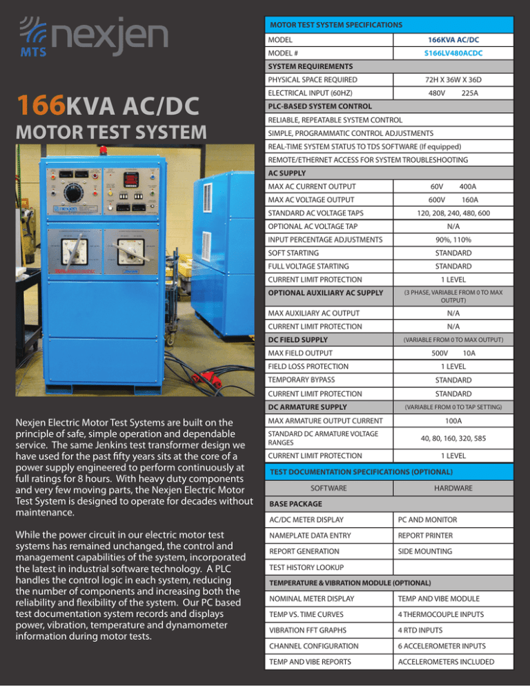
MOTOR TEST SYSTEM SPECIFICATIONS 166KVA AC/DC MODEL S166LV480ACDC MODEL # SYSTEM REQUIREMENTS PHYSICAL SPACE REQUIRED 166KVA AC/DC MOTOR TEST SYSTEM 72H X 36W X 36D ELECTRICAL INPUT (60HZ) 480V 225A PLC-BASED SYSTEM CONTROL RELIABLE, REPEATABLE SYSTEM CONTROL SIMPLE, PROGRAMMATIC CONTROL ADJUSTMENTS REAL-TIME SYSTEM STATUS TO TDS SOFTWARE (If equipped) REMOTE/ETHERNET ACCESS FOR SYSTEM TROUBLESHOOTING AC SUPPLY MAX AC CURRENT OUTPUT 60V 400A MAX AC VOLTAGE OUTPUT 600V 160A STANDARD AC VOLTAGE TAPS 120, 208, 240, 480, 600 OPTIONAL AC VOLTAGE TAP N/A INPUT PERCENTAGE ADJUSTMENTS 90%, 110% SOFT STARTING STANDARD FULL VOLTAGE STARTING STANDARD CURRENT LIMIT PROTECTION OPTIONAL AUXILIARY AC SUPPLY 1 LEVEL (3 PHASE, VARIABLE FROM 0 TO MAX OUTPUT) MAX AUXILIARY AC OUTPUT N/A CURRENT LIMIT PROTECTION DC FIELD SUPPLY N/A (VARIABLE FROM 0 TO MAX OUTPUT) MAX FIELD OUTPUT 500V FIELD LOSS PROTECTION While the power circuit in our electric motor test systems has remained unchanged, the control and management capabilities of the system, incorporated the latest in industrial software technology. A PLC handles the control logic in each system, reducing the number of components and increasing both the reliability and flexibility of the system. Our PC based test documentation system records and displays power, vibration, temperature and dynamometer information during motor tests. 1 LEVEL TEMPORARY BYPASS STANDARD CURRENT LIMIT PROTECTION STANDARD DC ARMATURE SUPPLY Nexjen Electric Motor Test Systems are built on the principle of safe, simple operation and dependable service. The same Jenkins test transformer design we have used for the past fifty years sits at the core of a power supply engineered to perform continuously at full ratings for 8 hours. With heavy duty components and very few moving parts, the Nexjen Electric Motor Test System is designed to operate for decades without maintenance. 10A (VARIABLE FROM 0 TO TAP SETTING) MAX ARMATURE OUTPUT CURRENT STANDARD DC ARMATURE VOLTAGE RANGES 100A 40, 80, 160, 320, 585 CURRENT LIMIT PROTECTION 1 LEVEL TEST DOCUMENTATION SPECIFICATIONS (OPTIONAL) SOFTWARE HARDWARE BASE PACKAGE AC/DC METER DISPLAY PC AND MONITOR NAMEPLATE DATA ENTRY REPORT PRINTER REPORT GENERATION SIDE MOUNTING TEST HISTORY LOOKUP TEMPERATURE & VIBRATION MODULE (OPTIONAL) NOMINAL METER DISPLAY TEMP AND VIBE MODULE TEMP VS. TIME CURVES 4 THERMOCOUPLE INPUTS VIBRATION FFT GRAPHS 4 RTD INPUTS CHANNEL CONFIGURATION 6 ACCELEROMETER INPUTS TEMP AND VIBE REPORTS ACCELEROMETERS INCLUDED 166KVA MOTOR TEST SUPPLY The 166KVA Motor Test Supply will run 150HP AC motors at full load and most 400HP motors at no load. (AC motors typically draw 25-35% of full load amps with no load). The DC supply will run most 150HP DC motors at full load, and will start and run most DC motors at no load. SOFTWARE TEST DOCUMENTATION PACKAGE (OPTIONAL) The Test Documentation Package ships with a PC and Printer, displays real-time AC and DC meter data during tests, records data to a searchable test database and prints a test report to be kept on file and/or provided to the client. (Test reports can be directly saved to ACS job folders). UPGRADES & ACCESSORIES TEMP AND VIBE MODULE The Temp and Vibe module is a portable data acquisition system that connects to the Test Documentation PC via a USB cable. It includes ports for 6 Accelerometers (sensors included), 4 Thermocouples and 4 RTDs. The software upgrade includes the display of Temperature and Vibration data on the meter screen, and graphical display of temperature vs. time curves and vibration fft's. (Optional) • Engineered for full-capacity AC and DC outputs at rated current for 8 hours. • Motor starting by current limited Soft starter or with full- voltage tap adjustments. • Independent, variable-voltage adjustment on DC Field and Armature Supplies. • Simple, push-button operation with intuitive controls, clear indicators and LED meters. • Industrial PLC provides reliable control, real-time system status, simple logic adjustments and remote troubleshooting. • Operator and System Safeties; E-stop, overload protection, trips and electrical interlocks. • Transformer Powered by Jenkins Electric Company. LEAD ISOLATOR BOX The Lead Isolator Box provides a safe method for isolating the connections between motor leads and test system leads. Fabricated from non-conductive material, the Lead Isolator Box keeps test operators safe from arching between lead connections. (Standard) POWERED BY 5933 Brookshire Boulevard • Charlotte, NC 28216 P: 704.969.7070 • F: 704.969.7071 • www.nexjenmotortest.com 2015


