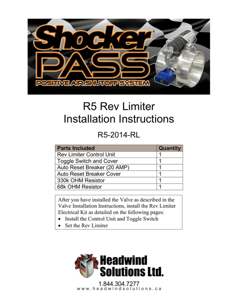
R5 Rev Limiter
Installation Instructions
R5-2014-RL
Parts Included
Rev Limiter Control Unit
Toggle Switch and Cover
Auto Reset Breaker (20 AMP)
Auto Reset Breaker Cover
330k OHM Resistor
68k OHM Resistor
Quantity
1
1
1
1
1
1
After you have installed the Valve as described in the
Valve Installation Instructions, install the Rev Limiter
Electrical Kit as detailed on the following pages:
Install the Control Unit and Toggle Switch
Set the Rev Limiter
Test the Rev Limiter Setting
Step 1: ELECTRICAL INSTALLATION
1. DISCONNECT BATTERIES
2. Mount the Control Unit on the firewall of the engine compartment away from moving parts and heat sources
so that it is accessible for set up and testing. Do not tighten the screws until after setup is complete.
3. Connect ground (black) wire and power (red) wire directly to the battery or power supply cables to the cab.
Install supplied 20 amp auto reset breaker (no fuses) in the power supply wire(red). Use crimp style heat
shrink connectors only.
DO NOT CONNECT TO FACTORY FUSE PANEL.
IMPROPER CONNECTIONS WILL VOID WARRANTY.
4. Install toggle switch on the left hand side of dash if possible, GROUND one side of the switch to the battery
or cab ground post.
5. Connect the harness as per the attached wiring diagram using crimp style heat shrink connectors.
6. Pulse pickup locations
–for light trucks see our website (under SUPPORT) for the chart of pulse locations. Supplied 68k resistor
may be required if signal source is inadequate.
–for heavy trucks, equipment and industrial equipment use a magnetic sensor mounted in the flywheel
housing.
-the alternator “R” (rectifier) terminal may be used but is NOT RECOMMENDED. The supplied 330K
resistor should be installed if alternator signal is inadequate.
7. RECONNECT BATTERIES
Step 2: Set the Rev Limiter (RPM Upper Limit)
Set the Rev Limiter for one of the following, as described below:
Variable Throttle
Work or Pump Mode
Constant Throttle
Setting the Rev Limiter for a Variable Throttle
Control Unit: Set Button
We recommend setting the shutdown RPM to a minimum of 20% above factory/OEM redline.
1. Turn the ignition key to the ON position, but do not start the engine.
2. On the Control Unit, press the SET button once. The GREEN LED on the front of the unit will illuminate.
3. Start the engine.
4. Raise the engine RPM to ½ (50%) of the desired shutoff RPM.
5. While holding the engine RPM steady, press and release the SET button. The GREEN LED will flash three
(3) times. Setup is now complete.
NOTE: The RED LED will strobe if no signal is detected. If so, check termination points and all
connections, and then repeat the above steps.
Setting the Rev Limiter for Work Mode (PTO Switch or Park Brake)
This should only be set for Work Mode, but can be used in conjunction with a variable throttle.
1. Turn the ignition key to the ON position, but do not start the engine.
2. Close the Work Mode Switch (e.g. PTO switch or park brake button).
3. On the Control Unit, press the SET button once. The GREEN LED on the front of the unit will illuminate.
4. Start the engine.
5. Raise the engine RPM to ½ (50%) of the desired shutoff RPM.
6. While holding the engine RPM steady, press and release the SET button. The GREEN LED will flash three
(3) times. Setup is now complete.
NOTE: The RED LED will strobe if no signal is detected. If so, check termination points and all connections,
and then repeat the above steps.
Setting the Rev Limiter for a Constant Throttle (Welders, Generators, Compressors,
etc.)
1. On the Control Unit, press and hold the SET button until the GREEN LED strobes. Release the button.
2. Start the engine, and allow the RPM to level off at the maximum work speed.
3. Press and release the SET button. The GREEN LED will flash three (3) times. Setup is now complete.
NOTE: The RED LED will strobe if no signal is detected. If so, check the termination points and all
connections, and then repeat the above steps.
Step 3: Test the Rev Limiter Setting
Testing the Setting for a Variable Throttle
1. Start the engine.
2. On the Control Unit, press the TEST button once.
The RED LED on the front of the unit will illuminate.
3. Throttle up the engine. The solenoid on the valve will
trip at the setting you made in the previous section.
Control Unit: LED and Test Button
4. If using a manual-reset valve, reset the valve by turning the
blue knob on it 90 degrees clockwise until it locks into position.
5. If using an auto-reset valve, it will automatically reset after the engine reaches and maintains 0 RPM for 17
seconds.
Testing the Setting for a Constant Throttle
1. On the Control Unit, press the TEST button once. The RED LED on the front of the unit will illuminate.
2. Start the engine. As the engine RPM rises, the solenoid on the valve will trip at 60% of the target RPM.
3. If using a manual-reset valve, reset the valve by turning the blue knob on it 90 degrees clockwise until it
locks into position.
4. If using an auto-reset valve, it will automatically reset after the engine reaches and maintains 0 RPM for 17
seconds.
NOTES:
The Valve will trip 7-10 times when activated by the Toggle Switch or at the preset RPM limit.
The solenoid will close the valve for 17 seconds after 0 RPM has been reached.
Installation and testing are now complete.
Thank you for choosing Shocker brand products.
See other side for wiring diagram
©2016 Headwind Solutions Inc. All rights reserved
780-672-2775 • Fax: 780-672-6411 • Toll Free: 1-844-304-7277
www.headwindsolutions.ca
V1.01/08 Mar. 2016

