Description The HIR-138.. Series are miniatured receiver for infrared
advertisement

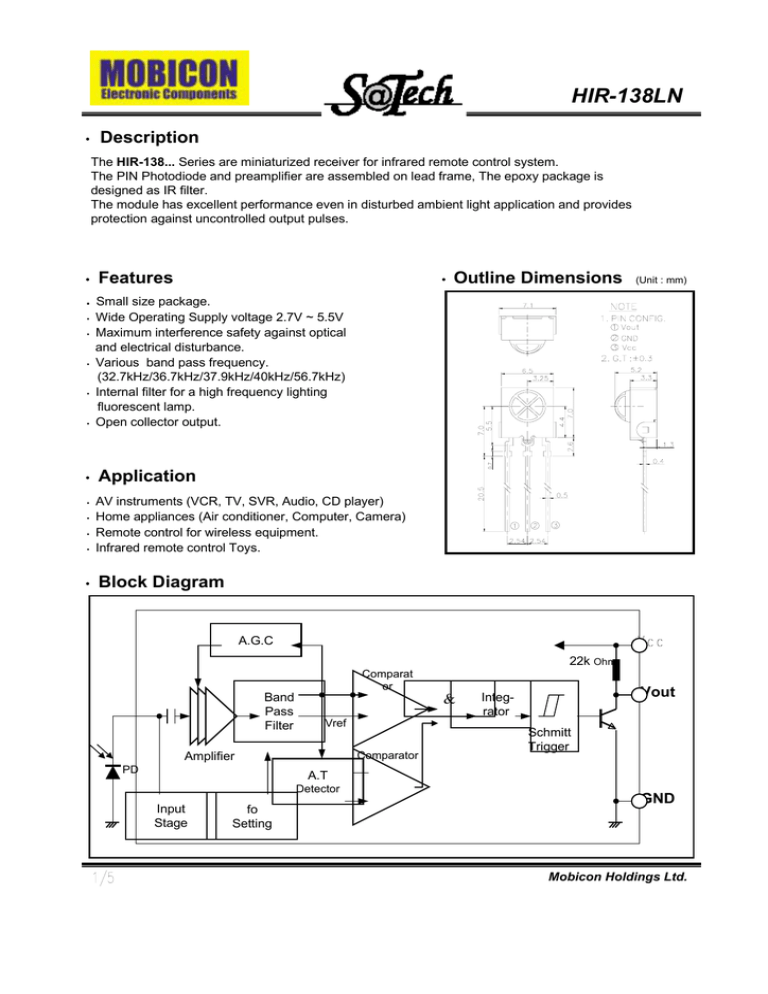
HIR-138LN • Description The HIR-138... Series are miniaturized receiver for infrared remote control system. The PIN Photodiode and preamplifier are assembled on lead frame, The epoxy package is designed as IR filter. The module has excellent performance even in disturbed ambient light application and provides protection against uncontrolled output pulses. • • • • • • • • • • • • • Features • Outline Dimensions (Unit : mm) Small size package. Wide Operating Supply voltage 2.7V ~ 5.5V Maximum interference safety against optical and electrical disturbance. Various band pass frequency. (32.7kHz/36.7kHz/37.9kHz/40kHz/56.7kHz) Internal filter for a high frequency lighting fluorescent lamp. Open collector output. Application AV instruments (VCR, TV, SVR, Audio, CD player) Home appliances (Air conditioner, Computer, Camera) Remote control for wireless equipment. Infrared remote control Toys. Block Diagram A.G.C 22k Ohm Comparat or Band Pass Filter & Vref Comparator Amplifier PD Vout Integrator Schmitt Trigger A.T Detector Input Stage fo Setting GND Mobicon Holdings Ltd. HIR-138LN Absolute Maximum Ratings Parameter Symbol (at 25°C Unless otherwise note) Ratings Unit Supply Voltage Output Current Operating Temperature Vcc Lout Topr 6.0 2.5 -10 ~ +60 V mA °C Storage Temperature Tstg -20 ~ +75 °C Soldering Temperature Tsol 260, t<5sec °C Ratings 2.7 ~ 5.5 30 ~ 60 Unit V kHz Recommended Operating Conditions Parameter Operating Voltage Input Frequency Symbol Vcc Fin Electro-Optical Characteristics Parameter Symbol Conditions Min Typ Max Unit Supply Voltage Vcc 2.7 5.5 V Supply Current Icc No signal input 0.8 1.5 mA 入 p Peak Wavelength(*1) 940 nm Arrival Distance(*1) L Standard Signal 7 10 m B.P.F Center Frequency(*2) fo 37.9 kHz Half Angle ø ±50 deg Vcc High Level Output Voltage(*1) VOH V -0.5 Low Level Output Voltage(*1) VOL 0.2 0.4 V High Level Output Pulse Width(*1) TWH 600 700 us Burst Wave =600us 500 Period = 1.2ms Low Level Output Pulse Width(*1) TWL 500 600 700 us Output Form Active Low Output (*1) Distance between emitter and detector specifies maximum distance that output wave form satisfies the standard (fig.2) under the conditions below against the standard transmitter. ON/OFF pulse width is to be satisfied within 0.3m ~ arrival distance length. u (*2)B.P.F center frequency (fo) for varies with model is show below Model B.P.F frequency (kHz) HIR-132OO HIR-136OO HIR-138OO HIR-140OO HIR-156OO 32.7 36.7 37.9 40.0 56.7 Mobicon Holdings Ltd. HIR-138LN Measurement Conditions • Output pulse width (Input burst waveform) 600 us Transmitter output Carrier Frequency(fo) Duty 50% 600 us 600 us (Output pulse) [ Fig1. Burst wave, Output wave ] • Standard Transmitter measurement circuit 10k ohm • Standard Transmitter Vcc 10uF Vout 10k ohm GND 20cm [ Fig2. Standard Transmitter ] • Test condition of arrival distance Vout osc Transmitt er GND Vcc : Indicates horizontal and vertical directions [ Fig3. Measurement condition for arrival distance ] Ambient light source : Detecting surface illumination shall be irradiate 200±50Lux under ordinary white fluorescence lamp without high frequency lighting 3/5 Mobicon Holdings Ltd. HIR-138LN Reliability Test Items Parameter Conditions High Temperature Ta=+60 Degree Celsius, Vcc=3.0V t = 240h High Temperature/High Humidity Ta=+40 Degree Celsius, 90%RH, Vcc=5.0V t = 240h Low Temperature Ta=-10 Degree Celsius, Vcc=5.0V t = 240h Heat Cycle Ta=-20 (0.5h)~+75 (0.5h), Degree Celsius 20 cycle Electro-optical characteristics shall be satisfied after leaving 2 hours in the normal temperature (Tamb = 25oC) 2.4 120 2.0 100 D istance(% ) S upply C urrent(弟) Typical Characteristics 1.6 1.2 0.8 80 60 40 20 0.4 0 0.0 2.5 3.0 3.5 4.0 4.5 5.0 5.5 2.5 6.0 3.0 3.5 Fig.1 Supply Current vs. Supply Voltage 5.0 5.5 6.0 Fig.2 Relative Distance vs. Supply Voltage 0 100 - 20 Di s t a n c e ( %) 4.5 S upply V oltage(V ) S upply Vo ltage(V) 120 4.0 - 30 80 - 40 - 50 60 - 10 10 20 30 40 50 - 60 60 40 - 70 20 0 - 20 - 10 0 10 20 30 40 50 60 70 70 - 80 80 - 90 90 80 Ambient Temperature(℃ ) Fig.3 Relative Distance vs. Ambient Temperature 4/5 Fig.4 Sensitivity Angle Characteristics for Reference Mobicon Holdings Ltd. HIR-138LN Standard Inspection 1 Among electrical characteristics, total quantity shall be inspected as below. 1-1 Front distance between emitter and detector 1-2 Current consumption 1-3 High level output voltage 1-4 Low level output voltage 2 Items except above mentioned are not inspected particularly, but shall fully satisfy. • Caution 1 The performance of remote control system depends on environments condition and ability of peripheral parts. Customer should evaluate the performance as total system in those conditions after system up with components such as commander, MICOM and this receiver module. 2 Store and use where there is no force causing transformation or change in quality. 3 Store and use when there is no extreme humidity 4 Solder the lead-pin within the condition of ratings. 5 To prevent static electricity damage to the Drive IC make sure that the human body, the soldering iron is connected to ground before using. 6 Put decoupling condenser(47uF~470uF) between Vcc and GND for reduce the noise from power supply line. • Others In case where any trouble or questions arise, both parties agree to make full discussion covering the said problem. 5/5 Mobicon Holdings Ltd.


