Hall Probe K for F3A Magnetic Field Transducers
advertisement

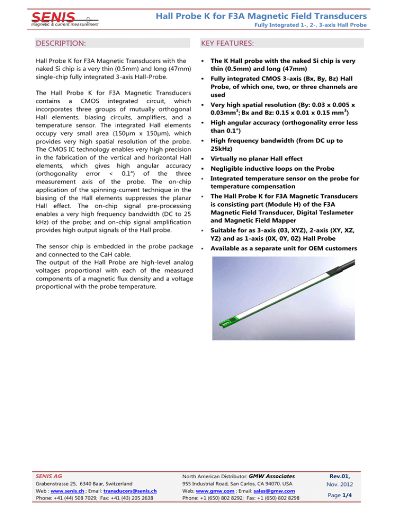
Hall Probe K for F3A Magnetic Field Transducers Fully Integrated 1-, 2-, 3-axis Hall Probe DESCRIPTION: KEY FEATURES: Hall Probe K for F3A Magnetic Transducers with the naked Si chip is a very thin (0.5mm) and long (47mm) single-chip fully integrated 3-axis Hall-Probe. The K Hall probe with the naked Si chip is very thin (0.5mm) and long (47mm) Fully integrated CMOS 3-axis (Bx, By, Bz) Hall Probe, of which one, two, or three channels are used Very high spatial resolution (By: 0.03 x 0.005 x 3 3 0.03mm ; Bx and Bz: 0.15 x 0.01 x 0.15 mm ) High angular accuracy (orthogonality error less than 0.1°) High frequency bandwidth (from DC up to 25kHz) Virtually no planar Hall effect Negligible inductive loops on the Probe Integrated temperature sensor on the probe for temperature compensation The Hall Probe K for F3A Magnetic Transducers is consisting part (Module H) of the F3A Magnetic Field Transducer, Digital Teslameter and Magnetic Field Mapper Suitable for as 3-axis (03, XYZ), 2-axis (XY, XZ, YZ) and as 1-axis (0X, 0Y, 0Z) Hall Probe Available as a separate unit for OEM customers The Hall Probe K for F3A Magnetic Transducers contains a CMOS integrated circuit, which incorporates three groups of mutually orthogonal Hall elements, biasing circuits, amplifiers, and a temperature sensor. The integrated Hall elements occupy very small area (150µm x 150µm), which provides very high spatial resolution of the probe. The CMOS IC technology enables very high precision in the fabrication of the vertical and horizontal Hall elements, which gives high angular accuracy (orthogonality error < 0.1°) of the three measurement axis of the probe. The on-chip application of the spinning-current technique in the biasing of the Hall elements suppresses the planar Hall effect. The on-chip signal pre-processing enables a very high frequency bandwidth (DC to 25 kHz) of the probe; and on-chip signal amplification provides high output signals of the Hall probe. The sensor chip is embedded in the probe package and connected to the CaH cable. The output of the Hall Probe are high-level analog voltages proportional with each of the measured components of a magnetic flux density and a voltage proportional with the probe temperature. SENIS AG Grabenstrasse 25, 6340 Baar, Switzerland Web : www.senis.ch ; Email: transducers@senis.ch Phone: +41 (44) 508 7029; Fax: +41 (43) 205 2638 North American Distributor: GMW Associates 955 Industrial Road, San Carlos, CA 94070, USA Web: www.gmw.com ; Email: sales@gmw.com Phone: +1 (650) 802 8292; Fax: +1 (650) 802 8298 Rev.01, Nov. 2012 Page 1/4 Hall Probe K for F3A Magnetic Field Transducers Fully Integrated 1-, 2-, 3-axis Hall Probe PROBE DIMENSIONS AND CHARACTERISTICS: Figure 1. The dimensions of K Hall probe and Cable (Module H) SENIS AG Grabenstrasse 25, 6340 Baar, Switzerland Web : www.senis.ch ; Email: transducers@senis.ch Phone: +41 (44) 508 7029; Fax: +41 (43) 205 2638 North American Distributor: GMW Associates 955 Industrial Road, San Carlos, CA 94070, USA Web: www.gmw.com ; Email: sales@gmw.com Phone: +1 (650) 802 8292; Fax: +1 (650) 802 8298 Rev.01, Nov. 2012 Page 2/4 Hall Probe K for F3A Magnetic Field Transducers Fully Integrated 1-, 2-, 3-axis Hall Probe Dimension [mm] Dimension A B C D E F 2.0 ± 0.1 5.0 ± 0.5 1.1 ± 0.2 3.2 ± 0.2 5.7 ± 0.2 4.8 ± 0.2 G H I J K [mm] Ø16 ± 1 47 ± 1 155 ± 5 35 ± 3 1800 ± 1% Dimension [mm] Dimension L M N 30 ± 2 50 ± 2 1950 ± 1% P R S T U V O 0.5 + 0.1/-0.0 [mm] 6.0 ± 0.1 2.7 ± 0.1 0.2 ± 0.1 0.15 0.64 1.1 ± 0.1 The “O” dimension and tolerance for the probe thickness is applied for the K Hall probes manufactured after January 2012. Those probes are labeled with Serial numbers beginning from xxx-12. The older K probes with thickness of 0.6 (+0.1/-0.0) mm (labeled with the Serial Numbers up to xxx11) are not longer in production. Table 1. The dimensions and tolerances of the K Hall probe and Cable (Module H) Figure 2. The reference Cartesian coordinate system of the K Hall probe Dimension X [mm] Y [mm] Z [mm] 0.15 0.01 0.15 Position of the center of MFSV (corresponding to MFSP, see Fig.1) 1.0 ± 0.1 -0.4 ± 0.05 -0.35 ± 0.1 Total Probe external dimensions 2.0 ± 0.1 0.5 +0.1/-0.0 47 ± 1 Magnetic field sensitive volume (MFSV) Angular accuracy of the axes ± 1° with respect to the reference surface CaH Cable Shielded, with a flexible thin part near the probe Total length of the CaH cable: Standard: 2 m (Probe notation: 03K02) Optional: xx m (Probe notation: 03Kxx) Note: Different lengths are available upon request. SENIS AG Grabenstrasse 25, 6340 Baar, Switzerland Web : www.senis.ch ; Email: transducers@senis.ch Phone: +41 (44) 508 7029; Fax: +41 (43) 205 2638 North American Distributor: GMW Associates 955 Industrial Road, San Carlos, CA 94070, USA Web: www.gmw.com ; Email: sales@gmw.com Phone: +1 (650) 802 8292; Fax: +1 (650) 802 8298 Rev.01, Nov. 2012 Page 3/4 Hall Probe K for F3A Magnetic Field Transducers Fully Integrated 1-, 2-, 3-axis Hall Probe INSTALLATION MANUAL FOR K HALL PROBE Warning: the Probe Tip is Fragile! The probe package is made of ceramics, and can be easily broken. Therefore, avoid any mechanical contact of the probe tip with other objects! Moreover, avoid the immersion of the probe of any liquid, and its exposure to moisture and aggressive gasses. The following precautions shall help ensure that the transducer accurate calibration remains preserved: 1. The mounting of the probe should be carried out by application of very low pressure to its back-end and thin wires. 2. If the probe head is clamped, the user should make sure that the substrate surface in contact with the reference plane of the probe is flat and covers as much of the probe reference surface as possible. 3. Do not apply more force than required to hold the probe in its place. 4. In order to prevent rupture of the thin wires from the probe head, the user should fix and secure the probe cable in the proximity of the probe. The thin wires of the flexible section of the cable may be folded with care; repeated strong bending should be avoided. 5. Also, avoid any high pressure and bending of the transient section between the thin and the thick cables: SENIS AG Grabenstrasse 25, 6340 Baar, Switzerland Web : www.senis.ch ; Email: transducers@senis.ch Phone: +41 (44) 508 7029; Fax: +41 (43) 205 2638 North American Distributor: GMW Associates 955 Industrial Road, San Carlos, CA 94070, USA Web: www.gmw.com ; Email: sales@gmw.com Phone: +1 (650) 802 8292; Fax: +1 (650) 802 8298 Rev.01, Nov. 2012 Page 4/4


