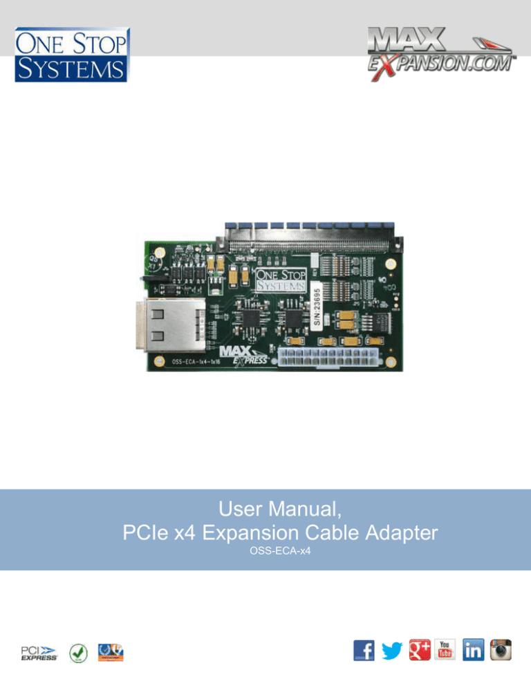
User Manual, PCIe x4 Expansion Cable Adapter
advertisement

User Manual, PCIe x4 Expansion Cable Adapter OSS-ECA-x4 Table of Contents 1. Components 1.a. Expansion cable adapter ..................................................................................................................... 3 1.b. Specifications ...................................................................................................................................... 3 2. Installation Instructions 2.a. Connecting PCIe cable ........................................................................................................................ 4 2.b. Removing PCIe cable .......................................................................................................................... 4 3. Technical Information 3.a. Switch settings..................................................................................................................................... 5 3.b. Block diagram ...................................................................................................................................... 6 3.c. PCI Express x4 Cable Connector ........................................................................................................ 7 4. Ordering Information One Stop Systems, Inc. Specifications subject to change without notice OSS-ECA-x4 Page 2 1. Components 1.a. Description The expansion cable adapter is a free-standing adapter board that transfers the PCIe bus from a x4 cable connector to a x4 link slot with a x16 connector. PCIe x16 Mechanical slot Connection (PCIe x4 electrically) PCIe x4 Cable Connector 1.b. Specifications Temperature • Operating temp: 0° to 50°C (32° to 122°F) ambient. • Short-term (30 mins) operating temp: –5°C to 55°C ambient. • Storage temp: –40°C to 70°C. Humidity • Operating humidity: 10-90% @ 40°C (non-condensing). • Storage humidity: 0-95% @ 40°C (non-condensing). Altitude • Operating altitude: 6000 ft. at operating temperature, 15,000 ft. at operated temperature. • Storage altitude: 40,000 ft. Vibration/Shock • Operating vibration: 5-17 Hz 0.5" double amplitude displacement; 72000Hz, 1.5g acceleration • Storage/transport vibration: 2g @ 5-500 Hz. • Operating shock: 20g @ 11 msec. • Storage/transport shock: 30g @ 11 msec. One Stop Systems, Inc. Specifications subject to change without notice OSS-ECA-x4 Page 3 2. Installation Instructions 2.a. Connecting PCIe cable 1) To install the PCIe cable, Insert into the expansion link board firmly or until you feel it lock into place. 2.b. Removing PCIe cable: 1) To remove PCIe cable pull back on green thumb tab to release metal pins and gently separate. One Stop Systems, Inc. Specifications subject to change without notice OSS-ECA-x4 Page 4 3. Technical Information 3.a. Switches settings The OSS-ECA-x4 contains two x8 micro switches that allow configuration of the Pericom PI2EQX4401D’s equalization, amplification and de-emphasis circuitry. The two switches, SW1 and SW2, are located above the Pericom devices on the front side of the PCB. 1 2 3 4 5 6 1 8 1 SW1 7 8 ON, low, 0, Up 8 OFF, high, 1, Down SW2 SW1 and SW2 Switch Location and Orientation Switch SW1 Settings Switch # Signal Name Default* Comments Up 1 ENABLE Down Switch SW2 Settings = Disable all Lanes Down = Normal operation Switch # 1 2 3 2 3 4 5 6 7 8 RX_SEL0 Up RX_SEL1 Up RX_SEL2 Up RX_SEL3 Up RX_SEL4 Up RX_SEL5 Up 2 3 RX_SEL6 4 Up 0 0 0 0 1 1 0 0 1 1 0 0 0 1 0 1 0 1 Rx Equalizer Selection See Table 1 4 5 6 Rx Amplifier Selection See Table 2 7 Table 1 8 Signal Name N/C TX_SEL 0 TX_SEL 1 TX_SEL 2 TX_SEL 3 TX_SEL 4 TX_SEL 5 Default * TX_SEL6 Down Not connected Up Up Tx Equalizer Selection See Table 1 Up Down Down Up Rx De-Emphasis Selection Equalization See Table 3 No Equalization 1.5db @ 1.25 GHz 2.5db @ 1.25 GHz 3.5db @ 1.25 GHz 4.5db @ 1.25 GHz 5.5db @ 1.25 GHz One Stop Systems, Inc. Specifications subject to change without notice Comments OSS-ECA-x4 Page 5 Tx Amplifier Selection See Table 2 Tx De-Emphasis Selection Table32 See Table 1 1 1 1 0 1 5.5db @ 1.25 GHz 7.5db @ 1.25 GHz 5 6 Swing 7 8 De-emphasis 0 0 0 1x 0 0 0db 1 0.8x 0 1 -2.5db 1 0 1.2x 1 0 -3.5db 1 1 1.4x 1 1 -4.5db 3.b. Block Diagram Clock* Clock* LVPECL Clock Buffer x4 PCIe Tx PCIe Signal Redriver x4 PCIe Rx PCIe Signal Redriver x4 PCIe Rx +3.3v CPRSNT# Downstream x4 PCI Express Cable Connector x4 PCIe Tx LEDs Cable Present/ Pwr LEDs PCIe lane status *Clock direction shown in Host configuration One Stop Systems, Inc. Specifications subject to change without notice Upstream x4 PCI Express Card Edge Connector OSS-ECA-x4 Page 6 3.c. Connectors PCIe x4 Card Edge Connector The pins are numbered as shown with side A on the top of the centerline on the solder side of the board and side B on the bottom of the centerline on the component side of the board. The PCIe interface pins PETpx, PETnx, PERpx, and PERnx are named with the following convention: “PE” stands for PCIe high speed, “T” for Transmitter, “R” for Receiver, “p” for positive (+), and “n” for negative (-). Note that adjacent differential pairs are separated by two ground pins to manage the connector crosstalk. PCI Express x4 Cable Connector The PCI Express x4 connector is a 38 position edge card connector with metallic shell as defined in the PCI Express External Cabling Rev 1.0, Molex part number 75586-0010, or equivalent. On the x4 connector, the pins are recessed far back inside the EMI Housing Guide (metallic shell) and are not easily accessed. PCI Express x4 Connector Pin Assignment Row B, Pin 19 Row A, Pin 1 Pin # A1 A4 A7 A10 A13 A16 B1 B4 B7 B10 B13 Cable Side 1 Cable Side 2 Pin # GND Drain Wires GND A1 A4 A7 A10 A13 A16 B1 B4 B7 B10 B13 A2 PETp0 Differential Pair PERp0 B2 A3 PETn0 Differential Pair PERn0 B3 A5 PETp1 PERp1 B5 PETn1 PERn1 B6 Cable Side 1 Cable Side 2 Differential Pair A6 Pin # A8 A9 A11 A12 PETp2 Differential Pair PETn2 PETp3 Differential Pair PETn3 CREFCLK+ Differential Pair A14 One Stop Systems, Inc. Specifications subject to change without notice Pin # PERp2 B8 PERn2 B9 PERp3 B11 PERn3 B12 CREFCLK+ A14 OSS-ECA-x4 Page 7 A15 A17 A18 A19 B2 B3 B5 B6 B8 B9 B11 B12 B14 B15 B16 B17 B18 B19 Backshell CREFCLK CREFCLK- A15 SB_RTN Hook-up Wire SB_RTN A17 CPRSNT# Hook-up Wire CPRSNT# A18 CPWRON Hook-up Wire CPWRON A19 PERp0 Differential Pair PETp0 A2 PETn0 A3 PETp1 A5 PETn1 A6 PETp2 A8 PETn2 A9 PETp3 A11 PETn3 A12 PERn0 PERp1 Differential Pair PERn1 PERp2 Differential Pair PERn2 PERp3 Differential Pair PERn3 PWR NC PWR B14 PWR NC PWR B15 PWR_RTN NC PWR_RTN B16 PWR_RTN NC PWR_RTN B17 CWAKE# Hook-up Wire CWAKE# B18 CPERST# Hook-up Wire CPERST# B19 Chassis Ground Overall Cable Braid Chassis Ground One Stop Systems, Inc. Specifications subject to change without notice Backshell OSS-ECA-x4 Page 8 4. Ordering Information OSS-ECA-x4 Related products KIT-EXP-2000- The expansion adapter kit with PCIe x4 Gen 1 host interface board (HIB2), PCIe x4 expansion cable adapter (ECA) with x16 connector, and PCIe x4 cable. One Stop Systems, Inc. Rev. A OSS-ECA-x4 Page 9


