Bandwidth of a Series Resonance Circuit If the series RLC circuit is
advertisement

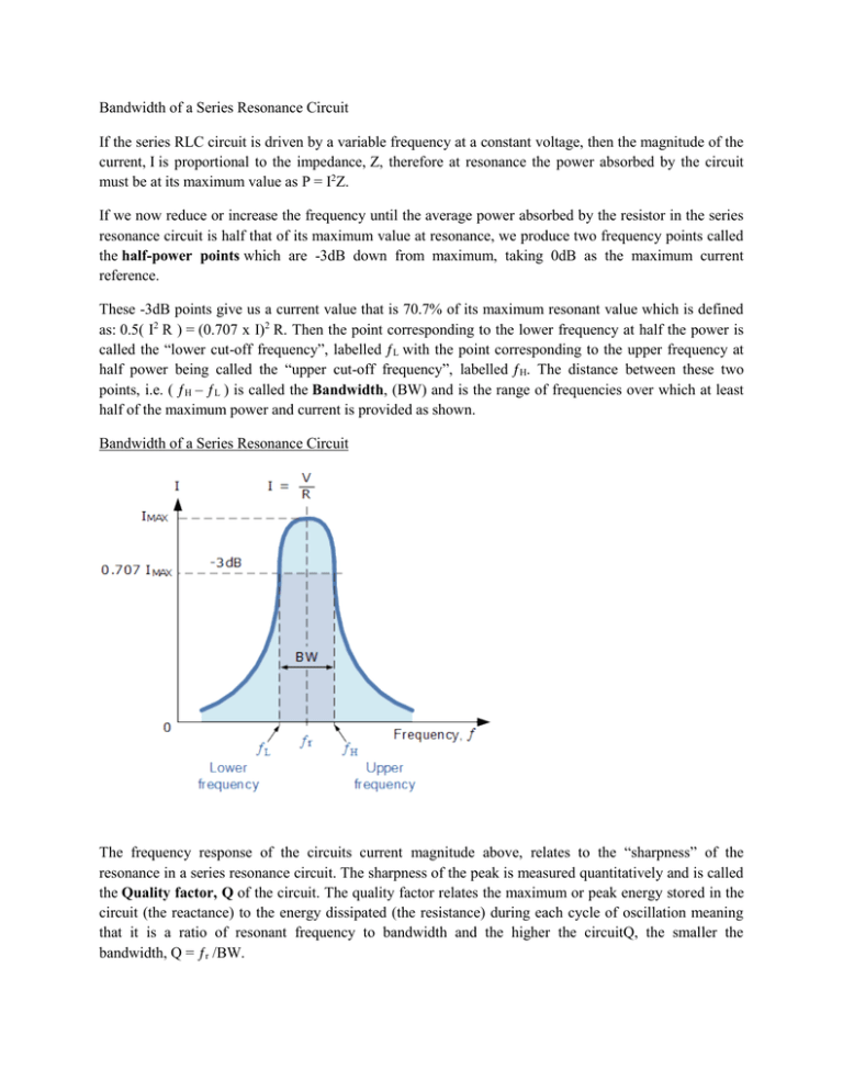
Bandwidth of a Series Resonance Circuit If the series RLC circuit is driven by a variable frequency at a constant voltage, then the magnitude of the current, I is proportional to the impedance, Z, therefore at resonance the power absorbed by the circuit must be at its maximum value as P = I2Z. If we now reduce or increase the frequency until the average power absorbed by the resistor in the series resonance circuit is half that of its maximum value at resonance, we produce two frequency points called the half-power points which are -3dB down from maximum, taking 0dB as the maximum current reference. These -3dB points give us a current value that is 70.7% of its maximum resonant value which is defined as: 0.5( I2 R ) = (0.707 x I)2 R. Then the point corresponding to the lower frequency at half the power is called the “lower cut-off frequency”, labelled ƒL with the point corresponding to the upper frequency at half power being called the “upper cut-off frequency”, labelled ƒH. The distance between these two points, i.e. ( ƒH – ƒL ) is called the Bandwidth, (BW) and is the range of frequencies over which at least half of the maximum power and current is provided as shown. Bandwidth of a Series Resonance Circuit The frequency response of the circuits current magnitude above, relates to the “sharpness” of the resonance in a series resonance circuit. The sharpness of the peak is measured quantitatively and is called the Quality factor, Q of the circuit. The quality factor relates the maximum or peak energy stored in the circuit (the reactance) to the energy dissipated (the resistance) during each cycle of oscillation meaning that it is a ratio of resonant frequency to bandwidth and the higher the circuitQ, the smaller the bandwidth, Q = ƒr /BW. As the bandwidth is taken between the two -3dB points, the selectivity of the circuit is a measure of its ability to reject any frequencies either side of these points. A more selective circuit will have a narrower bandwidth whereas a less selective circuit will have a wider bandwidth. The selectivity of a series resonance circuit can be controlled by adjusting the value of the resistance only, keeping all the other components the same, since Q = (XL or XC)/R. Bandwidth of a Series RLC Resonance Circuit Then the relationship between resonance, bandwidth, selectivity and quality factor for a series resonance circuit being defined as: 1). Resonant Frequency, (ƒr) 2). Current, (I) 3). Lower cut-off frequency, (ƒL) 4). Upper cut-off frequency, (ƒH) 5). Bandwidth, (BW) 6). Quality Factor, (Q) Series Resonance Example No1 A series resonance network consisting of a resistor of 30Ω, a capacitor of 2uF and an inductor of 20mH is connected across a sinusoidal supply voltage which has a constant output of 9 volts at all frequencies. Calculate, the resonant frequency, the current at resonance, the voltage across the inductor and capacitor at resonance, the quality factor and the bandwidth of the circuit. Also sketch the corresponding current waveform for all frequencies. Resonant Frequency, ƒr Circuit Current at Resonance, Im Inductive Reactance at Resonance, XL Voltages across the inductor and the capacitor, VL, VC ( Note: the supply voltage is only 9 volts, but at resonance the reactive voltages are 30 volts peak! ) Quality factor, Q Bandwidth, BW The upper and lower -3dB frequency points, ƒH and ƒL Current Waveform Series Resonance Example No2 A series circuit consists of a resistance of 4Ω, an inductance of 500mH and a variable capacitance connected across a 100V, 50Hz supply. Calculate the capacitance require to give series resonance and the voltages generated across both the inductor and the capacitor. Resonant Frequency, ƒr Voltages across the inductor and the capacitor, VL, VC


