User’s Guide
omega.com info@omega.com
U.S.A.:
Servicing North America:
Omega Engineering, Inc., One Omega Drive, P.O. Box 4047
Stamford, CT 06907-0047 USA
Toll-Free: 1-800-826-6342 (USA & Canada only)
Customer Service: 1-800-622-2378 (USA & Canada only)
Engineering Service: 1-800-872-9436 (USA & Canada only)
Tel: (203) 359-1660 Fax: (203) 359-7700
e-mail: info@omega.com
For Other Locations Visit omega.com/worldwide
The information contained in this document is believed to be correct, but OMEGA accepts no liability for any errors it contains,
and reserves the right to alter specifications without notice.
WARNING: These products are not designed for use in, and should not be used for, human applications.
Shop online at
omega.com ®
e-mail: info@omega.com
For latest product manuals:
omegamanual.info
MADE IN TAIWAN
WARRANTY/DISCLAIMER
OMEGA ENGINEERING, INC. warrants this unit to be free of defects in materials and workmanship for a period of 13 months from date
of purchase. OMEGA’s WARRANTY adds an additional one (1) month grace period to the normal one (1) year product warranty to
cover handling and shipping time. This ensures that OMEGA’s customers receive maximum coverage on each product.
If the unit malfunctions, it must be returned to the factory for evaluation. OMEGA’s Customer Service Department will issue an
Authorized Return (AR) number immediately upon phone or written request. Upon examination by OMEGA, if the unit is found to be
defective, it will be repaired or replaced at no charge. OMEGA’s WARRANTY does not apply to defects resulting from any action of
the purchaser, including but not limited to mishandling, improper interfacing, operation outside of design limits, improper repair, or
unauthorized modification. This WARRANTY is VOID if the unit shows evidence of having been tampered with or shows evidence of
having been damaged as a result of excessive corrosion; or current, heat, moisture or vibration; improper specification; misapplication;
misuse or other operating conditions outside of OMEGA’s control. Components in which wear is not warranted, include but are not
limited to contact points, fuses, and triacs.
OMEGA is pleased to offer suggestions on the use of its various products. However, OMEGA neither assumes
responsibility for any omissions or errors nor assumes liability for any damages that result from the use of its products
in accordance with information provided by OMEGA, either verbal or written. OMEGA warrants only that the parts
manufactured by the company will be as specified and free of defects. OMEGA MAKES NO OTHER WARRANTIES OR
REPRESENTATIONS OF ANY KIND WHATSOEVER, EXPRESSED OR IMPLIED, EXCEPT THAT OF TITLE, AND ALL IMPLIED
WARRANTIES INCLUDING ANY WARRANTY OF MERCHANTABILITY AND FITNESS FOR A PARTICULAR PURPOSE ARE
HEREBY DISCLAIMED. LIMITATION OF LIABILITY: The remedies of purchaser set forth herein are exclusive, and the total
liability of OMEGA with respect to this order, whether based on contract, warranty, negligence, indemnification, strict
liability or otherwise, shall not exceed the purchase price of the component upon which liability is based. In no event
shall OMEGA be liable for consequential, incidental or special damages.
CONDITIONS: Equipment sold by OMEGA is not intended to be used, nor shall it be used: (1) as a “Basic Component” under 10 CFR 21
(NRC), used in or with any nuclear installation or activity; or (2) in medical applications or used on humans. Should any Product(s) be
used in or with any nuclear installation or activity, medical application, used on humans, or misused in any way, OMEGA assumes no
responsibility as set forth in our basic WARRANTY / DISCLAIMER language, and, additionally, purchaser will indemnify OMEGA and hold
OMEGA harmless from any liability or damage whatsoever arising out of the use of the Product(s) in such a manner.
RETURN REQUESTS / INQUIRIES
Direct all warranty and repair requests/inquiries to the OMEGA Customer Service Department. BEFORE RETURNING ANY PRODUCT(S)
TO OMEGA, PURCHASER MUST OBTAIN AN AUTHORIZED RETURN (AR) NUMBER FROM OMEGA’S CUSTOMER SERVICE
DEPARTMENT (IN ORDER TO AVOID PROCESSING DELAYS). The assigned AR number should then be marked on the outside of the
return package and on any correspondence.
The purchaser is responsible for shipping charges, freight, insurance and proper packaging to prevent breakage in transit.
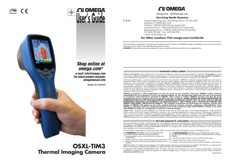
OSXL-TIM3
Thermal Imaging Camera
FOR WARRANTY RETURNS, please have the following
FOR NON-WARRANTY REPAIRS, consult OMEGA for current repair
information available BEFORE contacting OMEGA:
charges. Have the following information available BEFORE contacting
1. Purchase Order number under which the product was
OMEGA:
PURCHASED,
1. Purchase Order number to cover the COST of the repair,
2. Model and serial number of the product under warranty, and
2. Model and serial number of the product, and
3. Repair instructions and/or specific problems relative to the
3. Repair instructions and/or specific problems relative to the product.
product.
OMEGA’s policy is to make running changes, not model changes, whenever an improvement is possible. This affords our customers the
latest in technology and engineering. OMEGA is a registered trademark of OMEGA ENGINEERING, INC.
© Copyright 2014 OMEGA ENGINEERING, INC. All rights reserved. This document may not be copied, photocopied, reproduced,
translated, or reduced to any electronic medium or machine-readable form, in whole or in part, without the prior written consent of
OMEGA ENGINEERING, INC.
M5410/0714
Operating Manual for OSXL-TIM3 Thermal Imager Camera
The thermal imager camera can measure from -20~250°C (-4~482°F) and displays the thermal image and temperature.
Furthermore, thermal images can be saved to a micro SD card. Transferring images to the software is in cluded for image
report generation from these saved images.
Backlight
Selectable 5 levels of brightness.
Set Time
Set the date and time in MM/DD/YYYY (month/day/year) and HH/MM/SS (hour/minute/second) formats.
Time stamp
Turn on Time stamp to save thermal images with real-time stamp.
Turn off Time stamp to hide date and time on stored thermal images.
Erase Image
Select Yes, All image! to clear all stored thermal images.
Reset
Select Reset to recover the factory setting data.
Set parameter
Select Use Median Value to reduce noise in an image.
Select No Filter to display real image noise.
STORAGE & CLEANING
It should be stored at room temperature. The sensor lens is the most delicate part of the thermometer. The lens should be kept
clean at all times, care should be taken when cleaning the lens using only a soft cloth or cotton swab with water or medical alcohol.
Allowing the lens to fully dry before using the thermometer. Do not submerge any part of the thermometer.
BATTERIES
The thermometer incorporates visual low battery indication as follows:
* IP54 Splash Proof
OPERATION
1.
2.
3.
4.
5.
6.
Power on
Press Mode Key ( 2 ) or Trigger (10 ) to power on the unit.
Taking a thermal image and temperature
After power on, simply aim the thermal imager camer a at the measure target with
Lens ( 9 ) and get the thermal image and temperature immediately. Please make
sure the target area is within the field of view.
Note: There are three cursors on the screen. The cursor shows the temperature of
the object located in the middle of the screen. Other two moving cursors indicate the
highest and lowest temperatures in the thermal image.
Save thermal images
Press Trigger (10 ) to save the thermal image to the micro SD card, press Up Key ( 3 ) or
Down Key ( 4 ) to show the saved images. Press Mode Key ( 2 ) again to return to the
measurement screen.
Color palettes
Press Color Palette Key ( 6 ) to select the color palette (4 selectable color palettes) to view thermal images.
Ironbow
Rainbow
High contrast Grayscale
C/°F/K
Press Unit Key ( 5 ) for C °F or K transferred.
Power off
Press Mode Key ( 2 ) for more than 5 sec. to power off the unit. Auto power off time is around 30 sec..
‘Battery OK’: measurements
are possible
‘Battery Low’: battery needs to be
replaced, measurements are still possible
‘Battery Exhausted’ : measurements are
not possible
When the ‘Low Battery’ icon indicates the battery is low, the battery should be replaced immediately with AA, 1.5V batteries.
Please note: It is important to turn the instrument off before replacing the battery otherwise the thermometer may malfunction.
Dispose of used battery promptly and keep away from children.
SPECIFICATION
Thermal Image Resolution
32*31
Measurement Range
-20~250°C (-4~482°F)
2% of reading, or 2°C(4°F) whichever is greater
Accuracy (Tamb=20~26°C)
Thermal Sensitivity
0.1°C
Frame Rate
9Hz
Field of View
40*40 deg
Emissivity Range
0.95 default – adjustable 0.1 to 1 step .01
F ocus
F ocus free
LCD (inch)
2.8
LC D Type
C olor
Image Storage
Stores up to 60000 images/GB, BMP format.
Memory Type
Support 8G micro SD card
FUNCTIONS
Sensor Filter (um)
8~14um
Press Mode Key ( 2 ) for scrolling more display functions, then press Up key ( 3 ) or Down key ( 4 ) to change
the functions, then press Trigger ( 10 ) to confirm it.
The default emissivity is 0.95, or select other default emissivity: Matt:0.95, Semi-matt:0.8, Semi-glossy:0.6,
Glossy:0.3
Emissivity
Select Set value to adjust the emissivity (0.1 to 1 step .01).
Interface
USB
Battery Type
AA*4
Battery Life (hr)(backlit)
6
Dimensions
94.65 x 74.03 x 233.68mm (3.73 x 2.91 x 9.20 inch)
Weight
411 grams(14.5 oz) including batteries (AA*4pcs)
HAL
LAL
You can select Set Min temp or Set Max item to adjust the High Alarm (HAL) or Lo Alarm (LAL) limits
(step .1).
Language
Selectable Chinese or English.
EMC/RFI: Readings may be affected if the unit is operated within radio frequency electromagnetic field strength of approximately 3 volts per
meter, but the performance of the instrument will not be permanently affected.
Software Operating Instructions: OSXL-TIM3
STARTING UP
First you have to connect the application set to the power supply and the PC. Then start “TIM03ArraySW.exe”.
The next step is to initialize the interface. Depending on your system you have to choose the pursuant COM Port. You have to
regard the following steps:
1.) Connect the USB jack. If you want to connect the device directly to the computer, you have to use USB cable.
2.) Power up the device by connecting the power jack.
3.) Select “ COM* ” in the Interface-Combo-Box.
4.) Click “ Start ” in the Interface-Button. If TIM 03 is present, the GUI will show data in the dialogue.
PROGRAM FEATURES
This is a short overview of all functions of the program:
As you can see in the screenshot some elements are information-giving others are for control. First we will discuss the
information giving elements:
Item
Function
Pixel Screen
The Pixel Screen shows a calculated RGB-Value for the temperature or voltage each
thermopile sees.
Voltage/Temperature
This field shows a histogram. It represents the distribution of voltages or temperatures.
Distribution of all Pixels
Pixel Voltage/Temperature This field shows the voltage or temperature of all thermopiles.
False Color Scale
The False Color Scale shows the range of the chosen color scheme and the minimum and
maximum Value in the Pixel Screen.
Single Pixel Information Single Pixel Information shows several information of a pixel selected at the Pixel Screen by
mouse or keyboard (use arrows).
Note: If a setting in any dialogue-box is changed,
it must be confirmed with ENTER.
The control elements are:
Item
Set Interface : COM
Start/Stop
Moduletype
VDD
Function
Determine your COM port.
Protocol specifications :Transfer rate 460800 baud, 8 bata bits, no parity, 1 stop bit, NONE
Starts and stops capturing of data.
Thermopile sensor array is 32*31
Show Power supply voltage (3.3VDC ±2%, 300mA)
FPS
Set MCLK
Show Frames per second.
The clock for the ASIC, delivered by the microcontroller, can be decreased. So the ASIC works
slower. In temperature mode a decrease of the MCLK results in incorrect temperatures.
Set Framestack
Framestack allows integrating over multiple pictures for better quality because of noise reduction
by accepting a lower frame rate. The Framestack can get a size between 1 and 300.
Interpolate
Interpolation simulates a higher resolution, from 32x31 to 128x127 pixels for example.
Set Color Scheme
There are eight different color schemes available.
Save Values/Pixel to Excel Temperatures and Pixel:
saves Temperature- values table to Excel(TIM_TempV_*****.xls)
saves Pixels to Excel(TIM_Temp_*****.bmp)
Calibration-constants(w):
shows Calibration-constants in GUI and saves data to Excel (TIM_CalC_*****.xls)
Save Data Stream to File The data stream can be saved in a binary or a text file. For analysis the text files are easier
(Binary/Text/AV)
to handle.
First click “Save to…” and enter name, file type and destination where you want it to save. If you
are using a text file, you can enter the starting-pixel and the amount of pixels stored after that. For
example, entering 5 and 3 means the pixels 5, 6, 7 will be stored. This option does not exist for
binary files. To begin data capturing click “Rec” in the Save to File-Box. The Button is highlighted
red, as long as data capturing proceeds. You can stop recording by pressing “Stop” in the Save to
File-Box. The red highlighting of the Rec-Button disappears.
If you want to play the stored stream with your program, press “Play”. A new window appears.
Press “Open stream…” and open the desired file. Now enter the Frame rate, press enter and
confirm with play.
It is also possible to reduce the size of the file by setting the figure in the “Every Frame”-field to a
different amount. When “Every Frame” is set to 6, for example, then only each sixth frame is
recorded. This value is also used, when a recorded data stream is played.
Set Command
“K”: send continous binary temperature datastream(Uc-adc)[K*10]
“k” : read single temperature frame.
“x” : stops stream without prompt.
Options
Set temperatures in Kelvin/degree Celsius.
Set mirror frame: X-Axis/Y-Axis/Both.
Ref.No. 032013


