Instruction Manual Supplement
D103265X012
February 2009
FIELDVUE Instruments
Supplement to HARTR Communicating FisherR
FIELDVUER Instrument Instruction Manuals
Audio Monitor for HARTR Communications
The frequencies used for HART communications
are in the audible range—you can hear them! The
1200 and 2200 Hz waveforms sound similar to the
sounds you hear from a FAX machine’s phone
modem. This document outlines how to assemble a
device to monitor these audible waveforms and a
few suggestions on how to use it for troubleshooting.
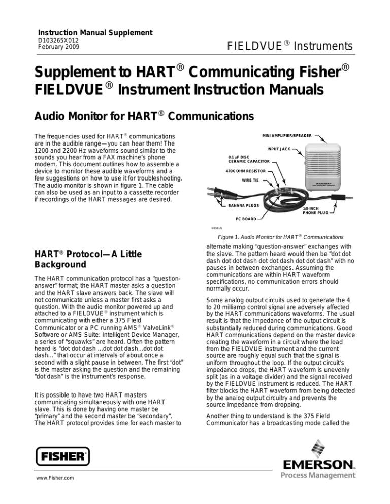
The audio monitor is shown in figure 1. The cable
can also be used as an input to a cassette recorder
if recordings of the HART messages are desired.
MINI AMPLIFIER/SPEAKER
INPUT JACK
0.1 μF DISC
CERAMIC CAPACITOR
470K OHM RESISTOR
WIRE TIE
BANANA PLUGS
1/8-INCH
PHONE PLUG
PC BOARD
W6943/IL
Figure 1. Audio Monitor for HART Communications
R
HART Protocol—A Little
Background
The HART communication protocol has a “questionanswer” format; the HART master asks a question
and the HART slave answers back. The slave will
not communicate unless a master first asks a
question. With the audio monitor powered up and
attached to a FIELDVUE instrument which is
communicating with either a 375 Field
Communicator or a PC running AMS ValveLink
Software or AMS Suite: Intelligent Device Manager,
a series of “squawks” are heard. Often the pattern
heard is “dot dot dash ...dot dot dash...dot dot
dash...” that occur at intervals of about once a
second with a slight pause in between. The first “dot”
is the master asking the question and the remaining
“dot dash” is the instrument’s response.
It is possible to have two HART masters
communicating simultaneously with one HART
slave. This is done by having one master be
“primary” and the second master be “secondary”.
The HART protocol provides time for each master to
www.Fisher.com
alternate making “question-answer” exchanges with
the slave. The pattern heard would then be “dot dot
dash dot dot dash dot dot dash dot dot dash” with no
pauses in between exchanges. Assuming the
communications are within HART waveform
specifications, no communication errors should
normally occur.
Some analog output circuits used to generate the 4
to 20 milliamp control signal are adversely affected
by the HART communications waveforms. The usual
result is that the impedance of the output circuit is
substantially reduced during communications. Good
HART communications depend on the master device
creating the waveform in a circuit where the load
from the FIELDVUE instrument and the current
source are roughly equal such that the signal is
uniform throughout the loop. If the output circuit’s
impedance drops, the HART waveform is unevenly
split (as in a voltage divider) and the signal received
by the FIELDVUE instrument is reduced. The HART
filter blocks the HART waveform from being detected
by the analog output circuitry and prevents the
source impedance from dropping.
Another thing to understand is the 375 Field
Communicator has a broadcasting mode called the
Instruction Manual Supplement
FIELDVUE Instruments
“shout” mode. If it doesn’t receive an answer to its
initial “question”, the 375 will ask again with a larger
signal strength. Demonstrate this by connecting the
audio monitor to the 375 without a FIELDVUE digital
valve controller attached. Power on the 375 and
listen to the HART messages. The pattern will be
something like this: “dot...dot...DOT...DOT...DOT”
where the capitalization indicates the louder attempt.
Troubleshooting Communications
Problems with the Audio Monitor
Several HART communication problems can be
identified with use of the audio monitor, a little
knowledge of the HART protocol, and a little
experience by the user in hearing differences
between normal HART communications and faulty
ones.
1. No response by slave device—Polling by a
master device that is not answered by a slave device
would sound like “ dot...dot...dot...” and would
continue for only a few times before the master
device would display a message stating that no
device was found. Corrective action would be to
determine why slave is not communicating.
2. Two masters of the same gender—If two
masters set to the same “gender” (primary or
secondary) were trying to communicate with the
same slave device, both would try to share their
“half” of the bandwidth. The basic pattern would still
be “dot dot dash ... dot dot dash...” as if there were
only one master but there might be some distortion
or extra characters as the messages overlap. The
pause in the middle would still be present. The
master device might suffer communications errors or
stop updating its readback values while in conflict.
Corrective action would be to have only one primary
and/or one secondary HART master communicating
at a time.
3. Current loop might need a FIELDVUE HART
filter—To determine if a current loop needs a HART
filter, configure ValveLink Software as “primary”
master and connect both it, a 375 Field
Communicator, and the audio monitor to a
FIELDVUE instrument powered by the current loop
2
February 2009
in question. Start both masters communicating to the
FIELDVUE instrument (something that keeps asking
for information, such as displaying the status of the
instrument condition information). Listen to the
waveforms on the audio monitor. If there are no
“Communication Errors” displayed on the masters
and the pattern sounds like “dot dot dash dot dot
dash dot dot dash dot dot dash”, things are probably
OK without a filter. If the pattern sounds like “dot dot
dash DOT DOT DASH dot dot dash DOT DOT
DASH” where one series is noticeably louder than
the other or like “DOT DOT DASH...DOT DOT
DASH...” where it sounds as if there is only one
master, a HART filter should be tried and the test
repeated. The louder sound or presence of only one
master’s messages where two should be present
indicates that the 375 Field Communicator is
operating in the “shout” mode to overcome a poor
HART circuit.
4. Noise on the HART circuit—If noise is present
on the HART circuit, depending on the frequency, it
can sound like clicks or static, tones which last for a
period of time, or a wavering of the existing HART
signal. Listen both while the HART messaging is
occurring and while there is no HART
communication (to sense the background noise).
The main thing about listening to noise is that it is
most likely random in nature but may be due to
system layout, construction methods, or the
unshielded operation of nearby equipment. For
trouble shooting purposes, use the audio monitor
before and after corrective action to reduce noise as
a way to detect whether the change is beneficial.
Construction
Figure 2 is the circuit diagram for the audio monitor.
Parts for constructing the audio monitor are listed
under Parts List.
Cut the circuit board material down to approximate
dimensions listed in the parts list. Solder the
capacitor, resistor and input and output wires
together on the circuit board. Secure the input and
output wires to the circuit board with the wire ties.
Cover the whole assembly with electrician’s tape.
Instruction Manual Supplement
FIELDVUE Instruments
February 2009
INPUT JACK
0.1uF
CAPACITOR
RED WIRE
470K OHM
RESISTOR
RED BANANA PLUG
BLACK WIRE
1/8” PHONE PLUG
BLACK BANANA PLUG
TO FIELDVUE DIGITAL
VALVE CONTROLLER
OUTPUT TO SPEAKER
MINI AMPLIFIER/SPEAKER
Figure 2. HART Communications Audio Monitor Circuit Diagram
Allow about one foot of wire on the output side and
attach the 1/8” phone plug (red wire to the center
post, black wire to shield). On the input side allow
about 3 feet of wire and attach the red banana plug
to the red wire and the black banana plug to the
black wire.
The 1/8” phone plug is connected to the input jack of
the amplifier/speaker box. The banana plugs are
either connected to the 375 Field Communicator
cable or are used with alligator clips or
Mini-grabber-style clips and connected to the “TALK
+/−” terminals of the FIELDVUE instrument.
Note
Neither Emerson, Emerson Process
Management, nor any of their affiliated
entities assumes responsibility for the
selection, use, or maintenance of any
product. Responsibility for the
selection, use, and maintenance of any
product remains with the purchaser
and end-user.
Description
Parts List
Note
Radio ShackR component part
numbers are specified as a suggested
way to obtain the components locally.
This is by no means an endorsement
of Radio Shack, or its products, or a
guarantee of their service,
functionality, or availability.
Quantity
Required
Radio Shack
Part Number
Mini Amplifier/Speaker
1
277-1008
0.1uF ceramic disc capacitor
1
272-135
470K ohm carbon resistor
1
271-1133
General-purpose
Component PC Board
0.5” x 1.75”
276-149
18AWG two-conductor
stranded wire
4 feet approx
278-567
Banana plugs
1 pair
274-730
1/8” Phone Plug
1
274-286
Nylon wire ties, 4 inch long
2
278-1632
Electrician’s tape
as needed
3
Instruction Manual Supplement
FIELDVUE Instruments
Related FisherR Documents
Bulletin 11.2:DLC3000 − Fisher FIELDVUE
DLC3000 Series Digital Level Controllers
(D102727X012)
Fisher
FIELDVUE
DLC3000 Series Digital
Level Controllers Instruction Manual (D102748X012)
Fisher FIELDVUE DLC3000 Series Digital
Level Controllers Quick Start Guide (D103214X012)
FIELDVUE DVC5000 Series Digital Valve
Controllers Instruction Manual
Note
The DVC5000 digital valve controller is
obsolete. Contact your Emerson
Process Management sales office if a
copy of this instruction manual is
needed.
February 2009
Bulletin 62.1:DVC6000 SIS − Fisher
FIELDVUE DVC6000 SIS Series Digital Valve
Controllers for Safety Instrumented System (SIS)
Solutions (D102784X012)
Fisher FIELDVUE DVC6000 SIS Series
Digital Valve Controllers for Safety Instrumented
System (SIS) Solutions Instruction Manual
(D103230X012)
Fisher FIELDVUE DVC6000 SIS Series
Digital Valve Controllers for Safety Instrumented
System (SIS) Solutions Quick Start Guide
(D103307X012)
Bulletin 62.1:DVC2000 − Fisher FIELDVUE
DVC2000 Series Digital Valve Controllers
(D103167X012)
Fisher FIELDVUE DVC2000 Series Digital
Valve Controllers Instruction Manual (D103176X012)
Fisher FIELDVUE DVC2000 Series Digital
Valve Controller Quick Start Guide (D103203X012)
Bulletin 62.1:DVC6000 − Fisher FIELDVUE
DVC6000 Series Digital Valve Controllers
(D102758X012)
Bulletin 62.1:HF300 − Fisher FIELDVUE
HF300 Series HART Filters (D102798X012)
Fisher FIELDVUE DVC6000 Series Digital
Valve Controllers Instruction Manual (D102794X012)
Fisher FIELDVUE HF300 Series HART
Filters Instruction Manual (D102796X012)
Fisher FIELDVUE DVC6000 Series Digital
Valve Controllers Quick Start Guide (D102762X012)
Fisher FIELDVUE LC340 Line Conditioner
instruction manual (D102797X012)
Fisher, FIELDVUE, AMS, and ValveLink are marks owned by one of the companies in the Emerson Process Management business division of
Emerson Electric Co. Emerson Process Management, Emerson, and the Emerson logo are trademarks and service marks of Emerson Electric Co.
HART is a mark owned by the HART Communication Foundation. All other marks are the property of their respective owners.
The contents of this publication are presented for informational purposes only, and while every effort has been made to ensure their accuracy, they
are not to be construed as warranties or guarantees, express or implied, regarding the products or services described herein or their use or
applicability. All sales are governed by our terms and conditions, which are available upon request. We reserve the right to modify or improve the
designs or specifications of such products at any time without notice. Neither Emerson, Emerson Process Management, nor any of their affiliated
entities assumes responsibility for the selection, use or maintenance of any product. Responsibility for proper selection, use, and maintenance of
any product remains solely with the purchaser and end-user.
Emerson Process Management
Marshalltown, Iowa 50158 USA
Sorocaba, 18087 Brazil
Chatham, Kent ME4 4QZ UK
Dubai, United Arab Emirates
Singapore 128461 Singapore
www.Fisher.com
4
Fisher
Controls International LLC 2006, 2009; All Rights Reserved


