L - Calclab
advertisement

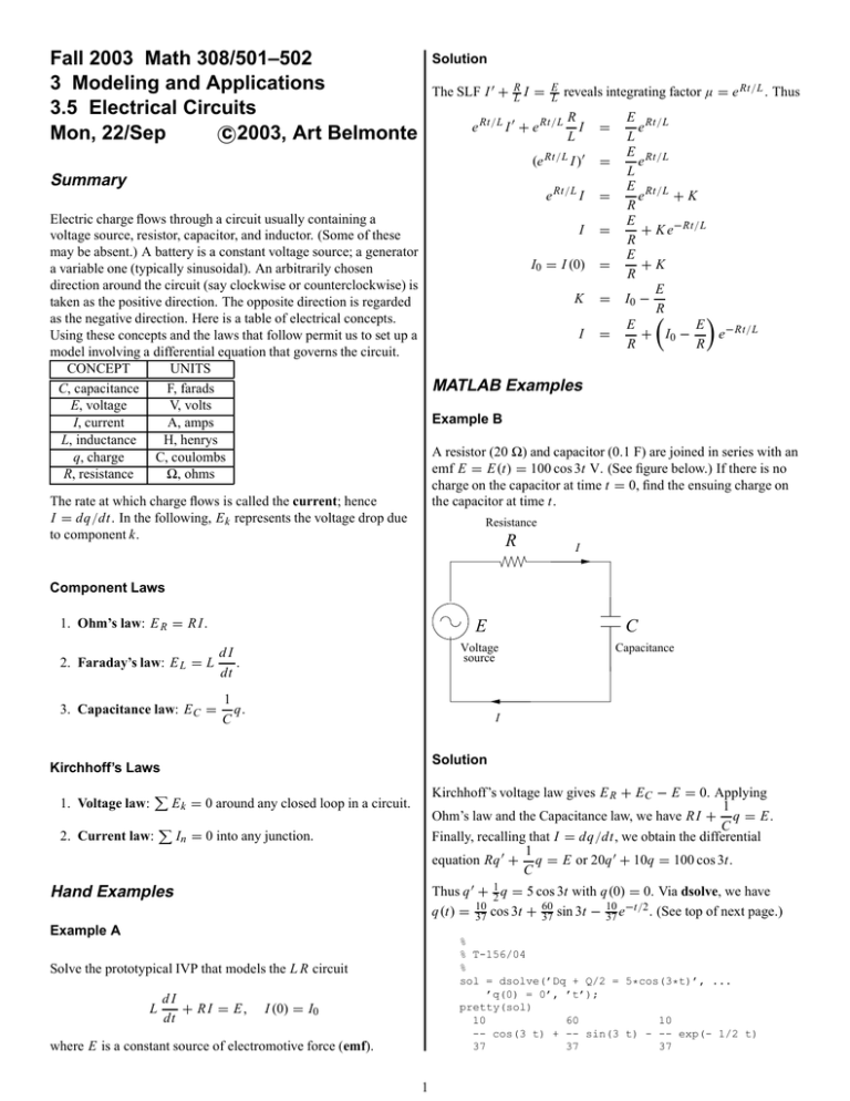
Fall 2003 Math 308/501–502 3 Modeling and Applications 3.5 Electrical Circuits c Mon, 22/Sep 2003, Art Belmonte Solution The SLF I 0 + R L I = E L R I L = (e Rt/L I )0 = e Rt/L I = e Rt/L I 0 + e Rt/L Summary reveals integrating factor µ = e Rt/L . Thus E Rt/L e L E Rt/L e L E Rt/L e +K R E + K e−Rt/L R E +K R E I0 − R E E + I0 − e−Rt/L R R Electric charge flows through a circuit usually containing a I = voltage source, resistor, capacitor, and inductor. (Some of these may be absent.) A battery is a constant voltage source; a generator I0 = I (0) = a variable one (typically sinusoidal). An arbitrarily chosen direction around the circuit (say clockwise or counterclockwise) is K = taken as the positive direction. The opposite direction is regarded as the negative direction. Here is a table of electrical concepts. I = Using these concepts and the laws that follow permit us to set up a model involving a differential equation that governs the circuit. CONCEPT UNITS MATLAB Examples C, capacitance F, farads E, voltage V, volts Example B I, current A, amps L, inductance H, henrys A resistor (20 ) and capacitor (0.1 F) are joined in series with an q, charge C, coulombs emf E = E(t) = 100 cos 3t V. (See figure below.) If there is no R, resistance , ohms charge on the capacitor at time t = 0, find the ensuing charge on The rate at which charge flows is called the current; hence the capacitor at time t. I = dq/dt. In the following, E k represents the voltage drop due Resistance to component k. R I Component Laws 1. Ohm’s law: E R = R I . E 2. Faraday’s law: E L = L dI . dt 3. Capacitance law: E C = 1 q. C Voltage source Solution P 2. Current law: Capacitance I Kirchhoff’s Laws 1. Voltage law: C Kirchhoff’s voltage law gives E R + E C − E = 0. Applying 1 Ohm’s law and the Capacitance law, we have R I + q = E. C Finally, recalling that I = dq/dt, we obtain the differential 1 equation Rq 0 + q = E or 20q 0 + 10q = 100 cos 3t. C E k = 0 around any closed loop in a circuit. P In = 0 into any junction. Thus q 0 + 12 q = 5 cos 3t with q(0) = 0. Via dsolve, we have 60 10 −t/2 q(t) = 10 . (See top of next page.) 37 cos 3t + 37 sin 3t − 37 e Hand Examples Example A % % T-156/04 % sol = dsolve(’Dq + Q/2 = 5*cos(3*t)’, ... ’q(0) = 0’, ’t’); pretty(sol) 10 60 10 -- cos(3 t) + -- sin(3 t) - -- exp(- 1/2 t) 37 37 37 Solve the prototypical IVP that models the L R circuit L dI + R I = E, dt I (0) = I0 where E is a constant source of electromotive force (emf). 1 Example C Solution A inductor (1 H) and resisitor (0.1 ) are joined in series with an emf E = E(t) = e−0.1t V. (See figure below.) If there is no current in the circuit at time t = 0, find the ensuing current in the circuit at time t. Kirchhoff’s voltage law gives E R + E C − E = 0. Applying 1 Ohm’s law and the Capacitance law, we have R I + q = E. C Finally, recalling that I = dq/dt, we obtain the differential 1 equation Rq 0 + q = E or 10q 0 + 5q = 10 sin(2πt). C Resistance R Thus q 0 + 12 q = sin(2πt) with q(0) = q0 for the various initial charges. Via dfield7, we have the following graph. Irrespective of the initial condition, the graphs eventually settle in to the so-called steady-state response. Beauty, eh? I E L q ’ = sin(2πt) − q/2 1 Inductance Voltage source q 0.5 I 0 −0.5 Solution Kirchhoff’s voltage law gives E L + E R − E = 0. Applying dI + R I = E or Faraday’s Law and Ohm’s law, we have L dt 1 0 −t/10 with I (0) = 0. Via dsolve, we have I + 10 I = e −t/10 I (t) = te . −1 0 % % T-156/08 % sol = dsolve(’DI + I/10 = exp(-t/10)’, ... ’I(0) = 0’, ’t’); pretty(sol) exp(- 1/10 t) t Example D An RC circuit (see figure below) contains a resistor (10 ) and a capacitor (0.2 F) linked in series with an emf E = E(t) = 10 sin(2πt). Use a numerical solver to sketch the graph of the charge on the capacitor versus time for the ICs q(0) = q0 = −1, −0.75, −0.5, . . . , 1. Use a time interval of 0 ≤ t ≤ 15 and superimpose all solutions on the same graph. Resistance R E I C Voltage source Capacitance I 2 5 t 10 15


