Development of Solid-State Transformer
advertisement

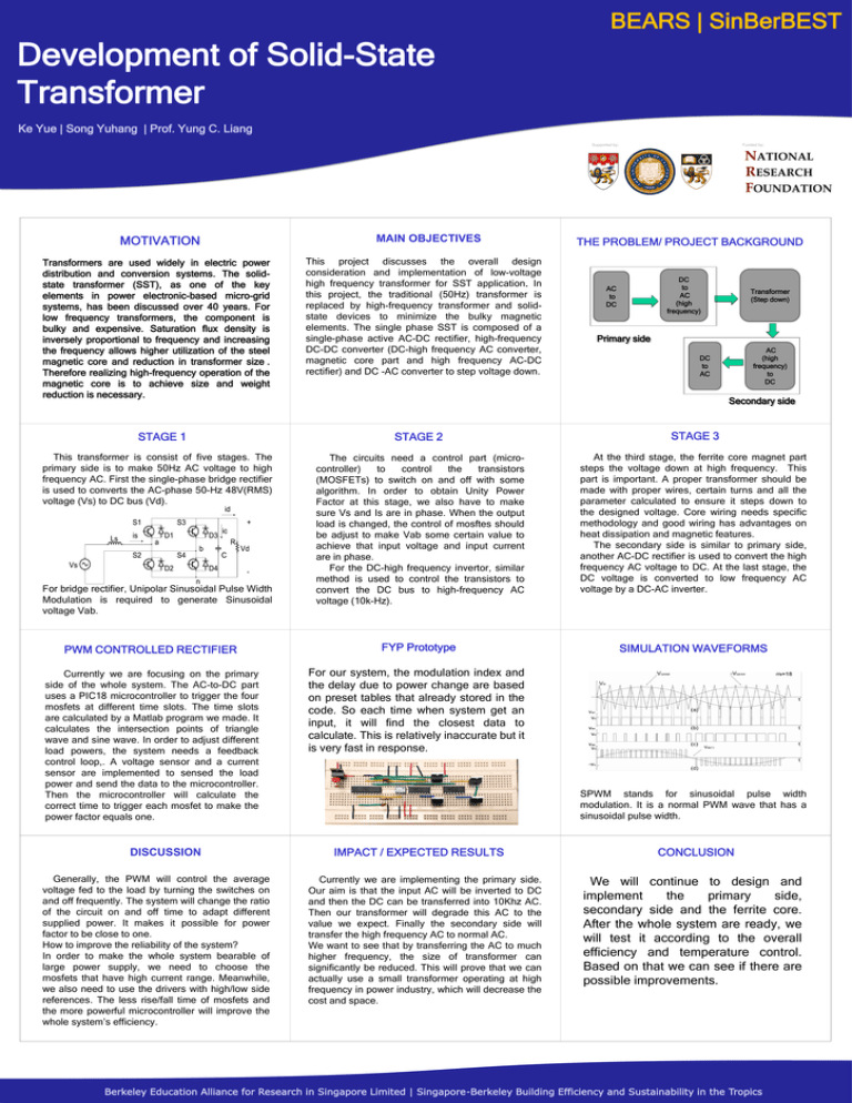
BEARS | SinBerBEST Development of Solid-State Transformer Ke Yue | Song Yuhang | Prof. Yung C. Liang Supported by: MOTIVATION Transformers are used widely in electric power distribution and conversion systems. The solidstate transformer (SST), as one of the key elements in power electronic-based micro-grid systems, has been discussed over 40 years. For low frequency transformers, the component is bulky and expensive. Saturation flux density is inversely proportional to frequency and increasing the frequency allows higher utilization of the steel magnetic core and reduction in transformer size . Therefore realizing high-frequency operation of the magnetic core is to achieve size and weight reduction is necessary. MAIN OBJECTIVES This project discusses the overall design consideration and implementation of low-voltage high frequency transformer for SST application. In this project, the traditional (50Hz) transformer is replaced by high-frequency transformer and solidstate devices to minimize the bulky magnetic elements. The single phase SST is composed of a single-phase active AC-DC rectifier, high-frequency DC-DC converter (DC-high frequency AC converter, magnetic core part and high frequency AC-DC rectifier) and DC -AC converter to step voltage down. Funded by: THE PROBLEM/ PROJECT BACKGROUND DC to AC (high frequency) AC to DC Transformer (Step down) Primary side AC (high frequency) to DC DC to AC Secondary side STAGE 2 STAGE 3 The circuits need a control part (microcontroller) to control the transistors (MOSFETs) to switch on and off with some algorithm. In order to obtain Unity Power Factor at this stage, we also have to make sure Vs and Is are in phase. When the output load is changed, the control of mosftes should be adjust to make Vab some certain value to achieve that input voltage and input current are in phase. For the DC-high frequency invertor, similar method is used to control the transistors to convert the DC bus to high-frequency AC voltage (10k-Hz). At the third stage, the ferrite core magnet part steps the voltage down at high frequency. This part is important. A proper transformer should be made with proper wires, certain turns and all the parameter calculated to ensure it steps down to the designed voltage. Core wiring needs specific methodology and good wiring has advantages on heat dissipation and magnetic features. The secondary side is similar to primary side, another AC-DC rectifier is used to convert the high frequency AC voltage to DC. At the last stage, the DC voltage is converted to low frequency AC voltage by a DC-AC inverter. PWM CONTROLLED RECTIFIER FYP Prototype SIMULATION WAVEFORMS Currently we are focusing on the primary side of the whole system. The AC-to-DC part uses a PIC18 microcontroller to trigger the four mosfets at different time slots. The time slots are calculated by a Matlab program we made. It calculates the intersection points of triangle wave and sine wave. In order to adjust different load powers, the system needs a feedback control loop,. A voltage sensor and a current sensor are implemented to sensed the load power and send the data to the microcontroller. Then the microcontroller will calculate the correct time to trigger each mosfet to make the power factor equals one. For our system, the modulation index and the delay due to power change are based on preset tables that already stored in the code. So each time when system get an input, it will find the closest data to calculate. This is relatively inaccurate but it is very fast in response. STAGE 1 This transformer is consist of five stages. The primary side is to make 50Hz AC voltage to high frequency AC. First the single-phase bridge rectifier is used to converts the AC-phase 50-Hz 48V(RMS) voltage (Vs) to DC bus (Vd). For bridge rectifier, Unipolar Sinusoidal Pulse Width Modulation is required to generate Sinusoidal voltage Vab. DISCUSSION Generally, the PWM will control the average voltage fed to the load by turning the switches on and off frequently. The system will change the ratio of the circuit on and off time to adapt different supplied power. It makes it possible for power factor to be close to one. How to improve the reliability of the system? In order to make the whole system bearable of large power supply, we need to choose the mosfets that have high current range. Meanwhile, we also need to use the drivers with high/low side references. The less rise/fall time of mosfets and the more powerful microcontroller will improve the whole system’s efficiency. SPWM stands for sinusoidal pulse width modulation. It is a normal PWM wave that has a sinusoidal pulse width. IMPACT / EXPECTED RESULTS Currently we are implementing the primary side. Our aim is that the input AC will be inverted to DC and then the DC can be transferred into 10Khz AC. Then our transformer will degrade this AC to the value we expect. Finally the secondary side will transfer the high frequency AC to normal AC. We want to see that by transferring the AC to much higher frequency, the size of transformer can significantly be reduced. This will prove that we can actually use a small transformer operating at high frequency in power industry, which will decrease the cost and space. CONCLUSION We will continue to design and implement the primary side, secondary side and the ferrite core. After the whole system are ready, we will test it according to the overall efficiency and temperature control. Based on that we can see if there are possible improvements. Funded by Berkeley Education Alliance for Research in Singapore Limited | Singapore-Berkeley Building Efficiency and Sustainability in the Tropics


