PLO-4000 - Microwave Dynamics
advertisement
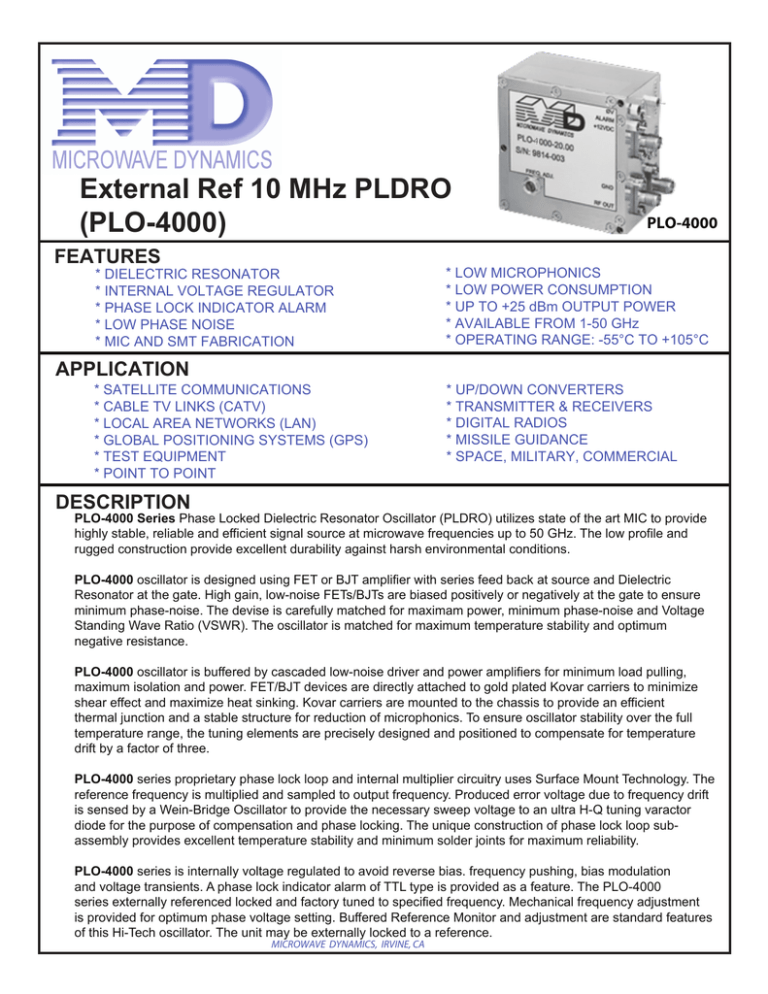
4 External Ref 10 MHz PLDRO (PLO-4000) FEATURES * DIELECTRIC RESONATOR * INTERNAL VOLTAGE REGULATOR * PHASE LOCK INDICATOR ALARM * LOW PHASE NOISE * MIC AND SMT FABRICATION APPLICATION * SATELLITE COMMUNICATIONS * CABLE TV LINKS (CATV) * LOCAL AREA NETWORKS (LAN) * GLOBAL POSITIONING SYSTEMS (GPS) * TEST EQUIPMENT * POINT TO POINT PLO-4000 * LOW MICROPHONICS * LOW POWER CONSUMPTION * UP TO +25 dBm OUTPUT POWER * AVAILABLE FROM 1-50 GHz * OPERATING RANGE: -55°C TO +105°C * UP/DOWN CONVERTERS * TRANSMITTER & RECEIVERS * DIGITAL RADIOS * MISSILE GUIDANCE * SPACE, MILITARY, COMMERCIAL DESCRIPTION PLO-4000 Series Phase Locked Dielectric Resonator Oscillator (PLDRO) utilizes state of the art MIC to provide highly stable, reliable and efficient signal source at microwave frequencies up to 50 GHz. The low profile and rugged construction provide excellent durability against harsh environmental conditions. PLO-4000 oscillator is designed using FET or BJT amplifier with series feed back at source and Dielectric Resonator at the gate. High gain, low-noise FETs/BJTs are biased positively or negatively at the gate to ensure minimum phase-noise. The devise is carefully matched for maximam power, minimum phase-noise and Voltage Standing Wave Ratio (VSWR). The oscillator is matched for maximum temperature stability and optimum negative resistance. PLO-4000 oscillator is buffered by cascaded low-noise driver and power amplifiers for minimum load pulling, maximum isolation and power. FET/BJT devices are directly attached to gold plated Kovar carriers to minimize shear effect and maximize heat sinking. Kovar carriers are mounted to the chassis to provide an efficient thermal junction and a stable structure for reduction of microphonics. To ensure oscillator stability over the full temperature range, the tuning elements are precisely designed and positioned to compensate for temperature drift by a factor of three. PLO-4000 series proprietary phase lock loop and internal multiplier circuitry uses Surface Mount Technology. The reference frequency is multiplied and sampled to output frequency. Produced error voltage due to frequency drift is sensed by a Wein-Bridge Oscillator to provide the necessary sweep voltage to an ultra H-Q tuning varactor diode for the purpose of compensation and phase locking. The unique construction of phase lock loop subassembly provides excellent temperature stability and minimum solder joints for maximum reliability. PLO-4000 series is internally voltage regulated to avoid reverse bias. frequency pushing, bias modulation and voltage transients. A phase lock indicator alarm of TTL type is provided as a feature. The PLO-4000 series externally referenced locked and factory tuned to specified frequency. Mechanical frequency adjustment is provided for optimum phase voltage setting. Buffered Reference Monitor and adjustment are standard features of this Hi-Tech oscillator. The unit may be externally locked to a reference. MICROWAVE DYNAMICS, IRVINE, CA SPECIFICATIONS Model Number Number Model Single Frequency Single Frequency Mechanical TuningRange Range Mechanical Tuning Power Output Power Output Load VSWR, Maximum Load VSWR, Maximum Power Requirements Power Requirements Reference Input Frequency Reference Input Frequency Reference Power Input Reference Power Input Range Frequency Stability Frequency Phase NoiseStability Phase Noise Spurious Spurious Harmonics Harmonics Alarm Alarm Operating Temperature Operating Temperature Storage Temperature Storage Temperature Connectors Connectors Size Size Finish Finish PLO-4000-XX.XX (Where XX.XXXX.XX is freq is infreq. GHz)in GHz) PLO-4000-XX.XX (Where 1.00 to 50.00 GHz 1.00 to 50.00 GHz 100 MHz 100 MHz +13 dBm,up to dBm +25 dBm Optional +13 dBm, up to + 25 Optional 2.0 :1.0 2.0: 1.0 +12, +15 VDC, 220 mA +12, +15 VDC,or220 mAOptional 10MHz 5MHz 10 or 50 MHz Optional dBm +10 dBm Same-6astoReference Same as Reference See Phase Noise Envelope (Fig. A) See Phase Noise Envelope (Fig. A) -80 dBc -80 dBc -25 dBc -25 dBc TTL TTL 0°C to-20º 50°C -55°C to 105°C Optional toStandard; +75ºC Optional to +100ºC -55°C-55º to 125°C 2.9 mm-Female SMA- Female SMA-Female or 2.92 or mm-Female 2.25" x 2.25" x 1.25" 2.25” x 2.25” 1.25” Nickel Nickel BLOCK DIAGRAM OSC -60 RF OUT AMP AMP -70 22 GHz -80 +15 VDC -90 -100 Regulator -120 -130 Error AMP/Alarm 1KHz 10KHz 50KHz 100KHz 400KHz 1MHz OFFSET FREQUENCY FROM THE CARRIER DET AMP RF IN External Crystal Ref. Ø Voltage FIGURE A .25 Ø x5 x10 4GHz -110 -140 AMP SSB PHASE NOISE -dBc/Hz PHASE NOISE ENVELOPE Alarm OUTLINE DRAWING 1.25 .09 2.070 .09 ØV +15V PLO-4000-XX.XX SERIAL NO. XXXX DATE CODE XXXX GND RF OUT .50 FREQ. ADJ .75 MNTG HOLES 2-56UNC-2B X .23 DP. 4 PLCS 2.25 MNTG HOLES .101 DIA. THRU 3 PLCS REF IN 2.070 2.25 2.070 1.100 ALARM NOTE: Drawing not to scale MICROWAVE DYNAMICS, 16541 Scientific Way, Irvine, CA PHONE: 949-679-7788 FAX: 949-679-7748 Web Page :http://www.microwave-dynamics.com • Email: info@microwave-dynamics.com .83 COPYRIGHT © 2006 MICROWAVE DYNAMICS, IRVINE CA • ORDERS ACCEPTED BY MICROWAVE DYNAMICS ARE SUBJECT TO OUR TERMS AND CONDITIONS OF SALE SPECIFICATIONS ARE SUBJECT TO CHANGE WITHOUT NOTICE
