transformers and inductive action
advertisement
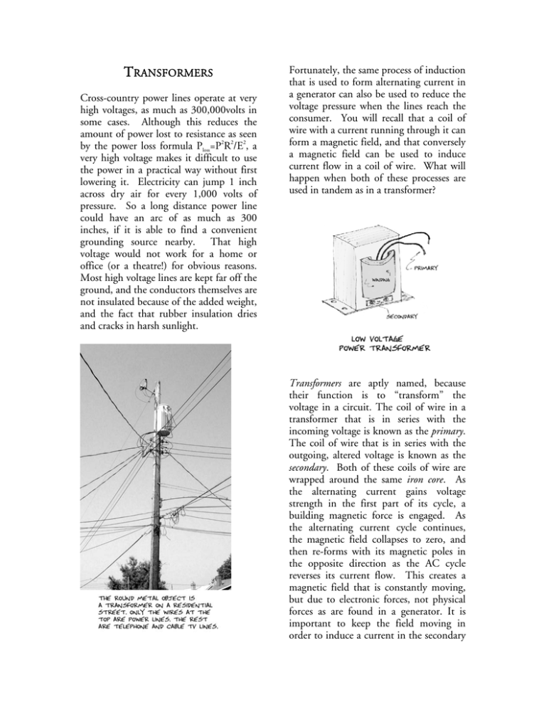
TRANSFORMERS Cross-country power lines operate at very high voltages, as much as 300,000volts in some cases. Although this reduces the amount of power lost to resistance as seen 2 2 2 by the power loss formula Ploss=P R /E , a very high voltage makes it difficult to use the power in a practical way without first lowering it. Electricity can jump 1 inch across dry air for every 1,000 volts of pressure. So a long distance power line could have an arc of as much as 300 inches, if it is able to find a convenient grounding source nearby. That high voltage would not work for a home or office (or a theatre!) for obvious reasons. Most high voltage lines are kept far off the ground, and the conductors themselves are not insulated because of the added weight, and the fact that rubber insulation dries and cracks in harsh sunlight. Fortunately, the same process of induction that is used to form alternating current in a generator can also be used to reduce the voltage pressure when the lines reach the consumer. You will recall that a coil of wire with a current running through it can form a magnetic field, and that conversely a magnetic field can be used to induce current flow in a coil of wire. What will happen when both of these processes are used in tandem as in a transformer? Transformers are aptly named, because their function is to “transform” the voltage in a circuit. The coil of wire in a transformer that is in series with the incoming voltage is known as the primary. The coil of wire that is in series with the outgoing, altered voltage is known as the secondary. Both of these coils of wire are wrapped around the same iron core. As the alternating current gains voltage strength in the first part of its cycle, a building magnetic force is engaged. As the alternating current cycle continues, the magnetic field collapses to zero, and then re-forms with its magnetic poles in the opposite direction as the AC cycle reverses its current flow. This creates a magnetic field that is constantly moving, but due to electronic forces, not physical forces as are found in a generator. It is important to keep the field moving in order to induce a current in the secondary A transformer that has the same number of turns of wire in both the primary and secondary is know as a 1:1 transformer, because the ratio of the input to the output is equal. Transformers of this type are generally used to isolate equipment from unwanted transient DC voltages. They are often found in sound equipment as a means of protecting PA speakers. Audio signals are AC voltages that have a variable period of cycle, usually between 30Hz and 30,000Hz. Since amplifiers use DC to power most of their circuitry, 1 to 1 transformers are used to isolate speakers from DC current that might accidentally form in the output line to the speakers. When a transformer is placed in the circuit, DC current is stopped, while the AC audio signal passes through. coil. The polarity of the flow in the secondary is exactly opposite to the polarity in the primary. The movement of the magnetic field in the primary induces an opposite, but equal current flow in the secondary if the coils of wire are equal in all aspects; but most importantly the number of turns around the core, and the proximity of the coil of wire to the iron core. This principle is used in a transformer for alternating current but will not work for a steady direct current. Even though DC develops a magnetic field in the coil of wire forming the primary as its voltage builds, once it has established the field it will remain in a steady state. Since the field is static and not moving, it will not continue to induce a current in the secondary coil. Transformers will pass an AC current, but will stop a DC current. Several other types of transformers are used to alter current flow in different ways. Probably the most common of these is the step-down transformer. TYPES OF T RANSFORMERS: The schematic drawing of a transformer gives us some clues to their construction. Power transformers are wrapped around a core made from sheets of laminated steel that help to focus the magnetic energy. The coils of wire at either side are shown relative to their size in the transformer. The primary is always shown to the left, and the secondary to the right. Step down transformers do the job of reducing voltage using the same physics principle of induction, first producing a magnetic field from electricity, and then electricity from a magnetic field. The voltage coming in to the primary is higher than the usable voltage at the secondary terminals. The change in voltage pressure results from a difference in the number of 2 windings that are in each of the coils. In a step-down transformer, there are more turns in the primary than there are in the secondary. Reducing the size of the secondary coil means that the coil cannot create as high a voltage. In a schematic drawing a step-down transformer is shown with fewer curls on the secondary side. The smaller, 6v coil supplies the lighting system, while the 24v output is used for relays and solenoids. Step-up transformers are just the opposite of the step down. They are used when a higher voltage is required for some specific piece of equipment. Fluorescent lights are a prime example of this, as are Neon lights. Both of these fixtures require a high voltage because they are types of arc lights, and have no filament. Instead the electrons must “arc” or jump across inside the lamp from one terminal to another. You will recall that the higher the voltage pressure, the more likely electrons are to jump across an open gap. TERMS USED IN THIS CHAPTER Transformer Primary Secondary Iron core Polarity Step-up transformers have more turns of wire in the secondary than they do in the primary. 1:1 Transformer Step-up Transformer Step-down Transformer Some transformers have more than one coil of wire in the secondary. Generally, one of the coils is much longer than the other. That allows one transformer to supply more than one output voltage in the secondary. This schematic drawing is for a transformer used in a pinball machine, which requires different voltages for different devices inside the cabinet. 3
