Solderless Breadboards
advertisement

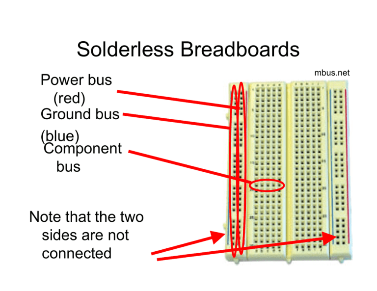
Solderless Breadboards Power bus (red) Ground bus (blue) Component bus Note that the two sides are not connected mbus.net Wiring Standards When possible, use wire colors for different types of signals: • Black: ground • Red: power • Other: various signals Clean Wiring A clean breadboard will make debugging easier – and it makes circuits more robust www.linefollowing.com tangentsoft.net Care with Power • Only insert components and wires into the breadboard when power is disconnected • “Wire, check-twice, then power” – Never reverse power and ground (this is a very common mistake) • Most chips that we will use expect +5V – More can destroy the chips – We will use DC/DC converters to step battery voltages down to +5V Wiring Procedure (Suggested) • • • • • • Power supply Power/ground buses Insert primary components Wire power/ground for components Add signals and remaining components Test incrementally Debugging Techniques • Multimeter: – Use voltage mode to check logic levels – Use continuity mode to confirm connections (but never with power turned on!) • Oscilloscope: – View voltage as a function of time on 2 channels • Test incrementally • Test intermediate sub-circuits Physical Interface for Programming AVR ISP Physical Interface for Programming AVR ISP USB connection to your laptop Physical Interface for Programming AVR ISP Header connection will connect to your circuit (through an adapter) Be careful when you plug your circuit in (check before powering) AVR ISPs are Cranky • When things are plugged in and powered, you should see two green LEDs on the ISP (on most units) • One red: usually means that your circuit is not powered • Flashing orange: connector is backwards! • Orange: the programmer is confused – Could be due to your circuit not being powered at 5V – Could be due to other problems – Check power and reboot the ISP Compiling and Downloading Code Preparing to program: • See the Atmel HOWTO • Install OS-appropriate AVR tools Do this for next time! Compiling and Downloading Code • Once the chip is programmed, the AVR ISP will automatically reset the processor; starting your program Hints • Use LEDs to show status information (e.g., to indicate what part of your code is being executed) • Remember: on the Arduino boards, there is a LED connected to port B, pin 7 • Have one LED blink in some unique way at the beginning of your program • Go slow: – Implement and test incrementally – Insert plenty of pauses into your code (e.g., with delay_ms()) Getting Hardware Help • Some exercises in class (come ready) • Office hours • Appointments Lab Procedures • No food or drink are allowed in the lab. • Before leaving the lab, please be sure to clean up your workspace. • Because some equipment may be in short supply, please coordinate with others who will need these resources • Never place dead components back into the stock (instead – give them to me or the TA) Lab Procedures • You may remove your own kit from the lab. • No other equipment or supplies may leave the lab without the permission of the monitor. • Please clear all guests with the lab monitor. • Unless you have prior permission, please do not handle the projects of other class members (or from other classes). Lab Procedures • Always check your wiring before you power up your circuit (especially your power and ground connections). • If you break something, please report it (don't just put it away). • You are expected to supply and configure your own laptop computers for project use Group Assignments Musts For Next Time • Atmel HOWTO: get your compiler tools installed – Even if you are not using Windoze, consider using an emulator so you can use AVRstudio • Subversion: install (see the downloads page)


