Installation Instructions
advertisement

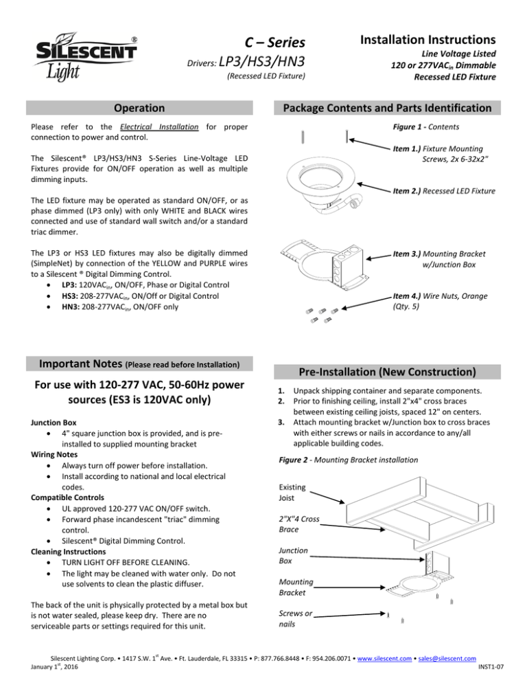
C – Series Drivers: LP3/HS3/HN3 (Recessed LED Fixture) Operation Installation Instructions Line Voltage Listed 120 or 277VACin Dimmable Recessed LED Fixture Package Contents and Parts Identification Please refer to the Electrical Installation for proper connection to power and control. Figure 1 - Contents Item 1.) Fixture Mounting Screws, 2x 6-32x2" The Silescent® LP3/HS3/HN3 S-Series Line-Voltage LED Fixtures provide for ON/OFF operation as well as multiple dimming inputs. Item 2.) Recessed LED Fixture The LED fixture may be operated as standard ON/OFF, or as phase dimmed (LP3 only) with only WHITE and BLACK wires connected and use of standard wall switch and/or a standard triac dimmer. The LP3 or HS3 LED fixtures may also be digitally dimmed (SimpleNet) by connection of the YELLOW and PURPLE wires to a Silescent ® Digital Dimming Control. LP3: 120VACin, ON/OFF, Phase or Digital Control HS3: 208-277VACin, ON/Off or Digital Control HN3: 208-277VACin, ON/OFF only Item 3.) Mounting Bracket w/Junction Box Item 4.) Wire Nuts, Orange (Qty. 5) Important Notes (Please read before Installation) For use with 120-277 VAC, 50-60Hz power sources (ES3 is 120VAC only) Junction Box 4" square junction box is provided, and is preinstalled to supplied mounting bracket Wiring Notes Always turn off power before installation. Install according to national and local electrical codes. Compatible Controls UL approved 120-277 VAC ON/OFF switch. Forward phase incandescent "triac" dimming control. Silescent® Digital Dimming Control. Cleaning Instructions TURN LIGHT OFF BEFORE CLEANING. The light may be cleaned with water only. Do not use solvents to clean the plastic diffuser. The back of the unit is physically protected by a metal box but is not water sealed, please keep dry. There are no serviceable parts or settings required for this unit. Pre-Installation (New Construction) 1. 2. 3. Unpack shipping container and separate components. Prior to finishing ceiling, install 2"x4" cross braces between existing ceiling joists, spaced 12" on centers. Attach mounting bracket w/Junction box to cross braces with either screws or nails in accordance to any/all applicable building codes. Figure 2 - Mounting Bracket installation Existing Joist 2"X"4 Cross Brace Junction Box Mounting Bracket Screws or nails Silescent Lighting Corp. • 1417 S.W. 1st Ave. • Ft. Lauderdale, FL 33315 • P: 877.766.8448 • F: 954.206.0071 • www.silescent.com • sales@silescent.com January 1st, 2016 INST1-07 C – Series Drivers: LP3/HS3/HN3 (Recessed LED Fixture) Installation Instructions Line Voltage Listed 120 or 277VACin Dimmable Recessed LED Fixture Electrical Installation 1. Once ceiling is finished and the light is to be installed, locate the GREEN wire protruding from the open end of the wire whip, and connect it to the safety ground. (See Figure 3) Figure 3 - Electrical Connections (ON/OFF Control and Dimmed) Dim (-) YELLOW Dim (+) PURPLE Note: The wires are strain relieved and will support the light as required during installation. Use the three wire nuts provided or a UL Listed equivalent for all connections. 2. 3. If ON/OFF or triac phase dimming is desired, connect the line power lead to the BLACK wire, and the neutral power lead to the WHITE wire. If this connection is reversed, the light will work, but not as efficiently. The PURPLE and YELLOW wires are not used in this configuration, and should be capped. (See Figure 3) If digital dimming is desired, begin by connecting the line power lead to the BLACK wire, and the neutral power lead to the WHITE wire. Additionally, connect POSITIVE lead from the Silescent® Dimming Control to the PURPLE wire, and the NEGATIVE dimming lead to the YELLOW wire. (See Figure 3) LINE Power In NEUTRAL WHITE BLACK To Safety GROUND GREEN Mechanical Installation 1. Attach the light fixture to the junction box: After completing the electrical connections, align the lighting fixture so that the two opposing mounting holes align with the mounting bracket. Secure the light fixture using the two provided fixture mounting screws. Do not over tighten fasteners. (See Figure 4) Figure 4 - Mounting Light Fixture to Bracket Mounting Bracket Silescent® Light Fixture Note: If threads of sheet-metal or self-tapping screws extend into a wiring compartment for a distance of more than 5 mm (0.2 in), the conductors shall be reliably positioned away from the projecting screws, or the conductors shall be sufficiently loose to prevent damage to the insulation. Light Fixture Attachment Screws #632 x 1" (Qty 2) Silescent Lighting Corp. • 1417 S.W. 1st Ave. • Ft. Lauderdale, FL 33315 • P: 877.766.8448 • F: 954.206.0071 • www.silescent.com • sales@silescent.com January 1st, 2016 INST1-07 C – Series Drivers: LP3/HS3/HN3 Installation Instructions (Recessed LED Fixture) Line Voltage Listed 120 or 277VACin Dimmable Recessed LED Fixture Technical Assistance If you have questions concerning the installation or operation of this product, call the Silescent® Lighting support center at 954-766-8448. Please provide exact item code and serial number when calling. Limited Warranty Silescent® Lighting Corp. will, at its option repair or replace any unit that is defective in materials within 5 years for models (AC3-XX and ES3-XX) from date of shipment. For warranty service, return unit to place of purchase or mail to Silescent® Lighting Corp. 1421 st SW 1 Avenue, Fort Lauderdale, FL 33315, postage prepaid. Troubleshooting 1) Light does not turn on (no dimmer installation): Check that the wiring is correct. Apply power (ON/OFF) to lights. The lights should come to full bright. If the light still does not operate correctly, or if the wiring is correct, undo the fixture wiring connections and remove the light fixture. Turn the power back on and measure the power input voltage on the power wires. The power input voltage should read between 90-305 VAC. If the power is correct then return the light to Silescent® Lighting Corp. for replacement. If no power voltage is measured, troubleshoot the installation and make sure that the power is available before reconnecting the light. 2) Light turns on but is flickering (no dimmer installation): If it is the only light that is flickering in a zone, check for loose connections. 3) Light does not turn on and/or is flickering (dimmer installation): Remove the dimmer switch and apply power directly to the light. Measure the power input voltage on the power wires. The power input voltage should read between 90-305 VAC. If no power voltage is measured, troubleshoot the installation and make sure that the power is available before reconnecting the light. If light still does not turn on, then return the light to Silescent® Lighting Corp. for replacement. If the light turns on, the dimmer switch is incompatible. Contact Silescent® Lighting Corp. for dimmer switch specification. Silescent Lighting Corp. • 1417 S.W. 1st Ave. • Ft. Lauderdale, FL 33315 • P: 877.766.8448 • F: 954.206.0071 • www.silescent.com • sales@silescent.com January 1st, 2016 INST1-07


