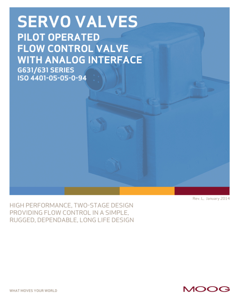
SERVO VALVES
PILOT OPERATED
FLOW CONTROL VALVE
WITH ANALOG INTERFACE
G631/631 SERIES
ISO 4401-05-05-0-94
Rev. L, January 2014
HIGH PERFORMANCE, TWO-STAGE DESIGN
PROVIDING FLOW CONTROL IN A SIMPLE,
RUGGED, DEPENDABLE, LONG LIFE DESIGN
WHAT MOVES YOUR WORLD
INTRODUCTION
Moog G631/631 Series Flow Control Servo Valves
Whenever the highest levels of motion control
performance and design flexibility are required, you’ll find
Moog expertise at work. Through collaboration, creativity
and world-class technological solutions, we help you
overcome your toughest engineering obstacles. Enhance
your machine’s performance. And help take your thinking
further than you ever thought possible.
TABLE OF CONTENTS
INTRODUCTION
Product Overview
3
Features and Benefits
4
Description of Operation
5
TECHNICAL DATA
Performance Characteristics
6
Dynamic Characteristics
7
Electrical Data
8
Installation Drawings and
Null Adjust Instructions
9
Hole Pattern for Mounting Surface
10
BACKGROUND
Null Flow Adjustment
11
Flow Calculation and Null Cut Options
12
Related Products
13
Routine Maintenance Guidelines
14
About Moog
15
ORDERING INFORMATION
Accessories and Spare Parts
17
Ordering Code
18
This catalog is for users with technical knowledge. To ensure all necessary characteristics for function and safety of the system, the user has
to check the suitability of the products described herein. The products described herein are subject to change without notice. In case of doubt,
please contact Moog.
Moog is a registered trademark of Moog Inc. and its subsidiaries. All trademarks as indicated herein are the property of Moog Inc. and its
subsidiaries. For the full disclaimer refer to www.moog.com/literature/disclaimers.
For the most current information, visit www.moog.com/industrial or contact your local Moog office.
Rev. L, January 2014
2
INTRODUCTION
Moog G631/631 Series Flow Control Servo Valves
PRODUCT OVERVIEW
The G631/631 Series flow control servo valves are
throttle valves for 3 and preferably 4-way applications.
They are a high performance, 2-stage design that covers
the range of rated flows from 5 to 75 l/min (1.3 to 20 gpm)
at 35 bar (500 psi) valve drop per spool land.
The output stage is a closed center, four-way sliding
spool. The pilot stage is a symmetrical double-nozzle
and flapper, driven by a double air gap, dry torque motor.
Mechanical feedback of spool position is pro­vid­ed by a
cantilever spring. The valve design is simple and rugged for
de­pendable, long life op­era­tion.
These valves are suitable for electrohydraulic position,
speed, pressure or force control systems with high dynamic
response requirements.
Valve design
2-stage, with spool and bushing and dry torque motor
Mounting pattern
ISO 4401-05-05-0-94
Maximum operating pressure to ports P, T, A, B
315 bar (4,500 psi)
Pilot stage
Nozzle Flapper
Rated flow at ∆pN 35 bar/spool land
(500 psi/spool land)
5 l/min
10 l/min
(1.3 gpm) (2.5 gpm)
20 l/min
(5 gpm)
40 l/min
(10 gpm)
60 l/min
(15 gpm)
75 l/min
(20 gpm)
Step response time for 0 to 100% stroke with spool and bushing design
18 ms
18 ms
18 ms
18 ms
18 ms
18 ms
TIIS
TIIS
Intrinsically safe valve versions are available for use in potentially hazardous environments. Specific models are certified to
FM, ATEX and CSA standards. Contact Moog for details.
Rev. L, January 2014
3
INTRODUCTION
Moog G631/631 Series Flow Control Servo Valves
FEATURES AND BENEFITS
The G631/631 Series is proven technology that performs
reliably in machines where high performance,
stability and accuracy are required. Moog’s Mechanical
Feedback Valves are designed to provide high reliability
and long service life.
Features Benefits
100% factory tested to ensure critical specification performance Ensures smooth and easy startup, reduces downtime and
insures long life in critical industrial applications
2-stage design Enables high machine performance, faster cycle times and greater accuracy - all resulting in higher productivity
Dual Coil torque motor Redundancy for high reliability
Dual Precision Nozzles in Torque Motor
Precision flow control and predictability
Dry torque motor design
Eliminates potential contamination issues in the air gaps of the torque motor that could cause machine downtime
Hardened 440C Bushing and Spool
Provides for high life, wear resistance when used in the harsh environments; provides for low sliding friction during use
Emergency failsafe positioning
Most valves are set up to return to a failsafe position when the command signal is interrupted or eliminated
Field replaceable pilot stage filter
Enables preventive maintenance in the field, saving precious machine downtime and service costs
External null bias adjustment
Enables technicians to manually adjust the null bias of the valve to adapt to the conditions of the machine (see section on null flow adjustment – Page 11). This feature provides a simple adjustment to machine performance without the need to adjust a controller.
Rev. L, January 2014
4
INTRODUCTION
Moog G631/631 Series Flow Control Servo Valves
DESCRIPTION OF OPERATION
The G631/631 Series Flow Control Servo Valve consists
of a polarized electrical torque motor and two stages
of hydraulic power amplification. The motor armature
extends into the air gaps of the magnetic flux circuit and
is supported in this position by a flexure tube member. The
flexure tube acts as a seal between the electromagnetic
and hydraulic sections of the valve. The 2 motor coils
surround the armature, one on each side of the flexure
tube.
The second stage is a conventional four-way spool design in
which output flow from the valve, at a fixed valve pressure
drop, is proportional to spool displacement from the null
position. A cantilevered feedback spring is fixed to the
flapper and engages a slot at the center of the spool.
Displacement of the spool deflects the feedback spring
which creates a force on the armature/flapper assembly.
Input signals induce a magnetic charge in the armature
and causes a deflection of the armature and flapper. This
assembly pivots about the flexure tube and increases the
size of one nozzle orifice and decreases the size of the
other.
The flapper of the first stage hydraulic amplifier is rigidly
attached to the armature. The flapper extends through the
flexure tube and passes between 2 nozzles, creating two
variable orifices between the nozzle tips and the flapper.
The pressure controlled by the flapper and nozzle variable
orifice is fed to the end areas of the second stage spool.
The differential pressure created by this action causes
spool motion. The resulting spool displacement induces a
linear force in the feedback wire which opposes the original
input signal torque. Spool movement continues until the
feedback wire force equals the input signal force.
Electro-hydraulic Servo Valve Cut-away
Magnets (not shown)
Coil
Upper Polepiece
Flexure Tube
Armature
Lower Polepiece
Electrical Connector
Flapper
Feedback Wire
Spool
Bushing
Inlet
Orifice
Pilot
Stage Filter
Rev. L, January 2014
X
T
A
P
B
View from ''T'' side
5
TECHNICAL DATA
Moog G631/631 Series Flow Control Servo Valves
G631/631 SERIES - SERVO VALVES
General Technical Data
Valve design
2-stage, with spool and busing and dry torque motor
Pilot stage Nozzle Flapper
Mounting pattern
ISO 4401-05-05-0-94
Installation postion
Any orientation, fixed or movable
Weight
2.2 kg (4.9 lb)
Storage temperature range
-40 to +60 °C (-40 to +140 °F)
Ambient temperature range
-40 to +135 °C (-40 to +275 °F)
Vibration resistance
30 g, 3 axis, 10 Hz to 2 kHz
Shock resistance
30 g, 3 axis
Seal material
Fluorocarbon (FKM) 85 Shore A
Others upon request
Hydraulic Data
Maximum operating pressure to ports P, A, B, X
315 bar (4,500 psi)
Maximum operating pressure to port T
20% of pilot pressure, max 100 bar (1,450 psi)
Rated flow at pN 35 bar/spool land (500 psi/spool land) 5, 10, 20, 40, 60, 75
Null adjust authority
Greater than 10% of rated flow
Hydraulic fluid
Hydraulic oil as per DIN 51524 parts 1 to 3 and ISO 11158 Other fluids on request.
Temperature range
-40 to +60 °C (-40 to +140 °F)
Recommended viscosity range
10 to 85 mm2/s (cSt)
Maximum permissible viscosity range
5 to 1,250 mm2/s (cSt)
Recommended cleanliness class as per ISO 4406
For functional safety
19/16/13
For longer life17/14/11
Recommended filter rating
For functional safety
ß10 ≤ 75 (10 µm absolute)
For longer lifeß5
≤ 75 (5 µm absolute)
Static
and Dynamic Data
Deviation of rated flow
± 10% of rated flow
Step response time for 0 to 100% stroke
18 ms
Threshold
1.0% of rated signal
Hysteresis
Null shift at
Rev. L, January 2014
∆ T = 38 °C (100 °F)
< 3% of rated signal
< 4% of rated signal
6
TECHNICAL DATA
Moog G631/631 Series Flow Control Servo Valves
75
50
25
+2
0
-2
-4
-6
90
-8
70
-10
50
30
10
0
0
10
20
30
40
50
0
5
10
Time (ms)
Step Response
Rev. L, January 2014
Phase Lag (Degrees)
100
Amplitude Ratio (Decibels)
Stroke (% of Rated Signal)
G631/631 SERIES SERVO VALVES
50
100
Frequency (Hz)
Standard Frequency Response
3,000PSI DTE -24 at 38° C (100° F)
±25% Input Amplitude
7
TECHNICAL DATA
Moog G631/631 Series Flow Control Servo Valves
ELECTRICAL DATA
Rated current and coil resistance
A variety of coils are available for G631/631 Series Servo
Valves, which offer a wide choice of rated ­currents.
Inductance is determined under pressurized operating
conditions and is greatly influenced by back electromagnetic
forces of the torque motor. These effects vary with
most operating conditions, and vary greatly with signal
frequencies above 100 Hz. The apparent coil inductance
values given are determined at 50 Hz.
Coil impedance
The resistance and inductance of standard coils are
given below. The 2 coils in each Servo Valve are wound
with equal turns giving a normal production tolerance
on coil resistance of ±12 %. Copper magnet wire is
used, so the coil resistance will vary significantly with
temperature. The effects of coil resistance changes can be
essentially eliminated through use of a current feedback
servoamplifier having high output impedance.
Ordering code Coil inductance [H]
Command signal
Coil restance
[Ohms/coil at
25°C (77°F)]
Power consumption [W]
Single coil
Series coil
Parallel coil
Single coil
Series coil
Parallel coil
Q
±30
±15
±30
300
0.27
0.14
0.14
R
±100
±50
±100
28
0.28
0.14
0.14
Ordering code
Coil inductance [H]
Measured at 50 Hz
Single coil
Series coil
Parallel coil
Q
2.0
7.0
2.0
R
0.2
0.8
0.2
Coil connections
A 4-pin electrical connector that mates with an
MS3106F14S-2S is standard. All 4 torque motor leads are
available at the connector so that external connections
can be made for series, parallel, or differential operation.
G631/631 Series Servo Valves can be supplied on special
order with other connectors or pigtail.
Configuration for valve opening P
B, A
Single
Series
A
BC
D
A (+), B (-) or C (+), D (-)
Rev. L, January 2014
A
T
Parallel BC
D
A (+), D (-), B and C connected A
BC
D
A and C (+), B and D (-)
8
TECHNICAL DATA
Moog G631/631 Series Flow Control Servo Valves
INSTALLATION DRAWINGS AND NULL ADJUST INSTRUCTIONS
54.0
(2.126)
1
A
B
PIN D
22.99
(0.905)
C
46.0
(1.811)
135
(5.31)
PIN B
D
C
6
4
119
(4.70)
5
A
B
127
(5.00)
97.30
(3.831)
106.40
(4.189)
58.0
(2.29)
77.0
(3.05)
121
(4.75)
2
1
2
3
4
5
6
70.0
(2.74)
D
PIN A
PIN C
3
Typical wiring schematic
Filter location
4X Ø 6.76 (0.266) thru
Ø 11.10 (0.437) to depth shown Mounting Holes
Null adjust cover. Remove for screw access (requires 1/8” hex key)
Connector mates with MS3106F14S-2S (Moog P/N: -49054F014S002S)
Optional Manual Override
Fluid:
Industrial hydraulic fluid per DIN 51524 parts 1 to 3 and
ISO 11158, maintained to ISO 4406 Code 19/16/13
recommended. Viscosity 10 to 85 mm2/s (cSt) at 38 °C (60 to 300 SUS at 100 °F)
Operating Temperature Range:
Fluid: -40 to +60 °C (-40 to +140 °F)
Ambient: -40 to +135 °C (-40 to +275 °F)
Rev. L, January 2014
Valve Phasing:
Flow out port B results when:
Series coils: B & C connected, A+, D-
Parallel coils: A & C connected, B & D connected, A+/B- or C+/D-
Single coils: A & C+, B & DNull Adjust:
Flow out port A results with the clockwise rotation of
the null adjust screw.
9
TECHNICAL DATA
Moog G631/631 Series Flow Control Servo Valves
G631/631 SERIES HOLE PATTERN FOR MOUNTING SURFACE
X
P
F4
X
Y
F2
A
B
T
F4
F3
Designation
P
A
B
T
X
F1
F2
F3
F4
Size Ø
Position X
mm
in
11.13
0.438 11.13
0.438
11.13
0.438
11.13
0.438
3.18
0.125
M6
1/4-20
M6
1/4-20
M6
1/4-20
M6
1/4-20
mm
in
27.0
1.063
16.69
0.657
37.31
1.469
3.20
0.126
-10.59
-0.417
0
0
54.0
2.126
54.0
2.126
0
0
Position Y
mm
in
6.32
0.249 21.41
0.843
21.41
0.843
32.51
1.280
7.39
0.291
0
0
0
0
46.02
1.812
46.02
1.812
Notes
1. Surface to which the valve is mounted requires flatness
of 0.03 mm (0.001 in) over 100 mm (3.94 in) and an
average finish Ra better than 0.8 µm (0.000032 in).
2. Ports:
P and T: 10 mm (0.390 in) diameter, counter-bored 15.75 mm (0.620) in) by 1.5 mm (0.061 in) deep
A and B: 9 mm (0.344 in) diameter, counter-bored 15.75 mm (0.620 in) by 1.5 mm (0.061 in) deep
X:
7.5 mm (0.295 in) diamter, counter-bored 11.75 mm (0.463 in) by 1.5 mm (0.061 in) deep
3. Recommended Seals:
90 durometer that is compatible with the hydraulic fluid.
P, A, B and T: 12 mm inside diameter by 2 mm cross-section
X: 8 mm inside diamter by 2 mm cross-section
4. Location of X port in valve body does not correspond to
ISO standards.
Conversion Instruction
For operation with internal or external pilot connection.
Pilot flow supply Screw and seal washer location (M4 X 6 DIN EN ISO 4762)
X
P
Internal P
closed
open
External X
open
closed
Rev. L, January 2014
10
BACKGROUND
Moog G631/631 Series Flow Control Servo Valves
NULL FLOW ADJUSTMENT
It is often desirable to adjust the null flow of a servo valve
independently of other system parameters. The mechanical
null adjustment permits convenient control function setups. Valves with mechanical null adjustment allow for at
least ±10% adjustment of null flow. Mechanical feedback
elements position the spool relative to the valve body for a
given input signal.
Mechanical Adjustment Procedure
Optional Manual Override Operation
The mechanical null adjustor is a hex socket adaptor
located behind the pan head screw in the motor cap (see
illustration below) which, when adjusted, provides control
of the spool position to obtain the desired flow null.
At times it may be convenient to activate the servo
valve manually rather than with an electrical control
signal. This can be done on the G631/631 series with the
optional manual override. With supply pressure applied,
rotating the manual override handle on the motor cap fully
counterclockwise will result in the right port pressure
increasing. Rotating the manual override handle on the
motor cap fully clockwise will result in the left port
pressure increasing.
Normal adjustment should require less than ± one turn.
Limit null screw adjustment to less than ± two turns.
Adjustment Procedure
a. Using a blade screwdriver, remove the null access screw
to permit adjustment of the hex socket setscrew.
b. Using a 1/8 inch Allen Wrench, adjust the setscrew to
obtain the desired flow null.
Note: Clockwise rotation of the null adjuster produces flow
out port A.
c. After the desired flow null has been obtained, replace the
null access screw.
Tools and Equipment
a. Blade screwdriver
b. Allen wrench set (1/8 inch)
Optional Manual Override
Rev. L, January 2014
11
BACKGROUND
Moog G631/631 Series Flow Control Servo Valves
FLOW CALCULATION
Q = QN
Q
QN ∆p
∆pN
∆p
∆ pN
Flow Diagram
Q [l/min (gpm)]
The actual flow is dependent upon electrical command
signal and valve pressure drop. The flow for a given valve
pressure drop can be calculated using the square root
function for sharp edge orifices.
190 (50)
152 (40)
114 (30)
76 (20)
actual flow
rated flow
actual pressure drop per spool land
rated pressure drop per spool land
75
60
38 (10)
3
G6
)
(20
40
)
(10
19 (5)
15 (4)
B
04
0
1-3
3
G6
B
03
0
1-3
3
G6
)
0 (5
B
05
0
1-3
3
G6
)
(15
B
06
0
1-3
2
11 (3)
5)
.
0 (2
7.5 (2)
1
5
4 (1)
3)
(1.
2B
00
-3
31
G6
3
G6
B
01
0
1-3
2 (0.5)
NULL CUT OPTIONS
28
14
21
(200) (300) (400)
70
(1000)
140
315
(2000)
(4500)
∆p [bar (psi)]
See Ordering Code for reference
I
Input Current
Default, without request for
optional cuts
Rev. L, January 2014
Q
Closed Center Spool Valves
Control Flow
Q
Open Center Spool Valves
Control Flow
Control Flow
Standard Axis Cut
I
Underlap
Zone
Input Current
Normally used in hydraulic motor
applications
Q
I
Overlap
Zone
Input Current
Normally used in failsafe
applications
12
BACKGROUND
Moog G631/631 Series Flow Control Servo Valves
RELATED PRODUCTS
Din Rail Modules - Analog Control Cards
Moog’s DIN rail mounted module analog control cards
are ideal for use in enclosures where space is limited.
Modules include servoamplifers, transducer conditioning
electronics, command and auxiliary function modules,
valve drive amplifiers, and power supplies. All of these
modules are CE marked and require a 24V DC supply. The
modules mount to standard 35mm DIN rail mount for easy
installation and removal.
Din Rail Module
Portable Valve Testers - Evaluates Valves in the Field
Valve testers are a cost effective method for evaluating
valves in the field. They provide a quick and easy means of
differentiating between hydraulic and electronic problems.
There are five models to choose from, each with different
levels of capability and flexibility to meet your specific
requirements. All valve testers have a compact, easily
portable design.
Valve Tester
Mounting Manifolds - Easier Installation and Maintenance
Various mounting manifolds are available for standard
industrial valves, including base and adapter types for
mounting and flushing requirements. Other hardware such
as bolts and connectors are also available.
Mounting Manifolds
The specific accessories you may need for a particular
model are listed in the relevant product catalogs and can
be ordered through your local office.
Filtration - Oil Filtration Requirements for Industrial Servo Systems
The most effective way to reduce life cycle costs of an
oil hydraulic system, regardless of the types of valve
used, is through close attention to contamination control.
For industrial servo systems the ideal system filter
arrangement is summarized as follows:
• Use a 10 micron (Beta 10 >= 75) high pressure filter
without by-pass just before the valve or critical parts
of the valve (e.g. pilot)
• Use a 3 micron (Beta 3 >= 75) low pressure filter in the
return or bypass line.
• Use a filter in the tank breather that is at least the
same filtration level as the finest filter in the system.
This recommendation is based on the fact that most servo
and proportional valves can accept the odd particle up to
25 microns so the pressure filter will protect the valve
from catastrophic failure. The real work is done by the low
pressure filter reducing the small particle contamination
which is the prime contributor to component wear and
silting.
Rev. L, January 2014
Hydraulic Filters
Assuming that the filters are properly dimensioned and
care is taken during initial installation and maintenance,
the aim should be to limit oil contamination to 16/13
(under ISO 4406:1987) or 19/16/13 (under ISO 4406:
1999).
For long life, the maximum levels per ISO 4406: 1987
and 1999 are 14/11 and 17/14/11, respectively.
It is important to note that these are maximum
contamination levels and with proper care and regular
filter change, significantly lower levels can and should
be achieved. Attention must also be paid to a number of
other factors that contribute to oil condition problems
such as elevated temperatures, high tank humidity,
“dirty” new oil, etc.
13
BACKGROUND
Moog G631/631 Series Flow Control Servo Valves
ROUTINE MAINTENANCE GUIDELINES
Every six months or 4,000 operating hours, check for
proper operation of the control valve assembly by
performing the preventative maintenance steps outlined
below. These checks do not require removal of the valve
from the process line. If a problem is suspected, repair the
valve assembly prior to returning the unit to service.
• Replace the hydraulic filter element
• Stroke the valve and check for smooth, full-stroke
operation; unsteady motion could indicate a servo
valve, actuator or process valve problem
STORAGE CONDITIONS
We recommend the following ambient conditions for
storage:
• Dust-free, moderately ventilated
• As vibration-free and shock-free as possible
Shock resistance (as per EN 60068-2-27):
50 g, 6 directions, half-sine 3 ms
Vibration resistance (as per EN 60068-2-6): 30 g, 3 axes, frequency 10 to 2,000 Hz
GENERAL INFORMATION
Temperature
Effects when Storing Valves
The following effects may occur when storing valves for
a long time:
• Sealing materials become brittle, possibly resulting
in leaks
• Hydraulic fluid becomes gummy, possibly resulting in
friction
Recommended: +15 to +25 °C (+59 to +77 °F)
Permissible: -40 to +60 °C (-40 to +140 °F)
Temperature fluctuations >10 °C (50 °F) must be
avoided.
Distance to shielded radiators: > 1 m (3 ft)
No direct exposure to sunlight
No sources of light with a high UV content
Storage Time
The storage time starts at stock receipt and ends at
mounting of the valve.
UV rays generate ozone, which damage sealing
materials.
Relative air humidity: < 65 %, non condensing
Preservatives
If preservation is carried out, use only preservatives
which are compatible with the sealing materials and do
not affect the valve, spare parts and accessories.
BEFORE STORAGE
Note: If the valves are exposed to aggressive
environmental influences during storage, vacuum
packaging may be necessary. We recommend the
following preparatory measures for storage:
Mount the shipping plate on the valve.
This is the only way of adequately protecting the valves
against the ingress of dirt and moisture and protecting
the seals against the effects of ozone and UV.
Put the valve, spare parts and accessories into the
original packaging.
Package each valve separately.
Enclose anti-tarnish paper or package the valve, spare
parts and accessories with corrosion inhibiting film.
(Only for storage time > 1 year.)
Multipacks of single valves in their individual packages
are allowed.
Seal the original packaging properly.
This is the only way of adequately protecting the valves,
spare parts and accessories against damage.
Rev. L, January 2014
AFTER STORAGE
We recommend to check the original packaging, valve,
spare parts and accessories for possible damage or
alterations due to storage, that is, before use.
Damaged or not functional valves, spare parts and
accessories must not be started up.
Sealing materials with the following characteristics
must not be used:
• Contamination
• Cracking
• Hardening/softening
• Stickiness
• Discoloration
Storage Time > 5 Years
We recommend that the valve be checked by us or one
of our authorized service centers after a storage time
of more than 5 years.
Storage Time > 10 Years
After a storage time of more than 10 years the valves
have to be checked by us or one of our authorized
service centers.
14
BACKGROUND
Moog G631/631 Series Flow Control Servo Valves
ABOUT MOOG
Moog Inc. is a worldwide designer, manufacturer and
integrator of precision control components and systems.
Moog’s Industrial Group designs and manufactures
high performance motion control solutions combining
electric, hydraulic, and hybrid technologies with expert
consultative support in a range of applications including
energy production and generation machinery, industrial
production machinery and simulation and test equipment.
We help performance-driven companies design and
develop their next-generation machines.
Moog maintains facilities in 26 countries around the globe.
This vast scope ensures that our engineers remain close
to the needs of machine builders and provide flexible
design solutions and technical expertise tailored to our
customers’ toughest challenges.
Moog experts work in close collaboration with machine
builders and application engineers to design motion
control systems for greater productivity, higher reliability,
superior connectivity, less costly maintenance and more
effective operations. Our regional presence, industry
knowledge and design flexibility ensures Moog motion
control solutions are tailored to their environment—
from meeting operating regulations and performance
standards, to taking machine performance to a higher
level.
Servo Valves
Active Cartridge Valves
Products
At the heart of every Moog solution is an array of products
engineered for precision, high performance and reliability.
For more than six decades, Moog products have been
specified for critical machine applications.
Some are developed specifically for unique operating
environments. Others are standard equipment on
machines across many industries. All are continuously
improved to take advantage of the latest technology
breakthroughs and advancements.
Radial Piston Pumps
Moog products include:
•
Servo Valves and Proportional Valves
•
Servo Motors and Servo Drives
•
Servo Controllers and Software
•
Radial Piston Pumps
•
Actuators
•
Integrated Hydraulic Manifold Systems and Cartridge
Valves
•
Slip Rings
•
Motion Bases
Rev. L, January 2014
Servo Drives
15
BACKGROUND
Moog G631/631 Series Flow Control Servo Valves
ABOUT MOOG
Hydraulic solutions
Since Bill Moog invented the first commercially viable
servo valve in 1951, Moog has set the standard
for world-class hydraulic technology. Today, Moog
products are used in a variety of applications providing high power, enhanced productivity and ever
better performance for some of the world’s most
demanding applications.
Electric solutions
Clean operation, low noise generation, less
maintenance and reduced power consumption
make Moog electric solutions ideal for applications
worldwide. Moog is the ideal partner for applications
where transitioning technologies requires special
expertise.
Flight Simulation
Hybrid solutions
By incorporating the advantages of existing hydraulic
and electric technologies - including modular
flexibility, increased efficiency and cleanliness into innovative hybrid solutions, Moog offers new
performance potential in specialized applications.
Formula One Simulation Table
Moog Global Support
Moog Global Support is our promise to offer world-class
Repair and Maintenance Services delivered expertly by our
trained technicians. With the reliability only available from
a leading manufacturer with facilities around the world,
Moog offers you service and expertise you can count on to
keep your equipment operating as it should.
This promise offers many benefits to our customers
including:
• Flexible programs, tailored to your needs such as
upgrades, preventative maintenance and annual/
multi-year contracts
• On-site services bring the expertise to you, providing
quicker commissioning, set-up and diagnostics
• Access to reliable services that are guaranteed to
offer consistent quality anywhere in the world
For more information on Moog Global Support visit www.moog.com/industrial/service.
• Reduce your downtime by keeping critical machines
running in peak performance
• Protect your investment by ensuring reliability,
versatility and long-life of products
• Better plan your maintenance activities and make
systematic upgrades
• Leverage our flexible programs to meet the unique
service requirements of your facility
Look to Moog for global support including:
• Repair services using OEM parts are performed by
trained technicians to the latest specifications
• Stock management of spare parts and products to
prevent unplanned downtime
Rev. L, January 2014
16
ORDERING INFORMATION
Moog G631/631 Series Flow Control Servo Valves
ACCESSORIES AND SPARE PARTS
Series Dependent Accessories and Spare Parts
Accessories G631/631 Series
Part designation
Description
Attachment screws
4 required M8x45 ISO 4762-10.9 (5/16-18NC by 1.75 long) tightening
Metric Torque 13 Nm (11.5 lbf-in)
Attachment screws
4 required 5/16-18NC by 1.75 long tightening torque 13 Nm (11.5 lbf-in)
Inch
Mating connector
4 pin electrical connector
Mounting manifold
Base mounting manifold
Flushing plate
Manifold employed in place of valve when initially cleaning hydraulic fluids
AMO manifold
Adjustable metering orifice manifold used to bleed fluid between A and B
ports for better pressure control
Safety manifold
Sandwich manifold used to lock, extend and retract cylinder upon loss
of electrical signal or hydraulic pressure
Part number
B64929-007B070
C66391-144B
B46744-004 (-49054F014S002S) [MS3106F14S-2S]
B52576AM001
B67728-002
B64820AM003
B64291AMNNXXXX
Spare Parts G631/631 Series
Part designation
Base O-ring for P, T, A and B ports
Description
Material
5 required for P, T, A, and B ports 12 mm
Fluorocarbon FKM 85 shore
(0.472 in) inside diameter x 2.0 mm (0.079 in)
cross section.
Part number
A25163-012-020
(G2141-012-020)
X port O-ring
1 required 8.0 mm (0.315 in) x 2.0 mm (0.079 in)
cross section. A25163-008-020
(G2141-008-020)
Replaceable filter,
100 µm nominal
A67999-100
Filter replacement kit
Contains the following:
B52555RK200K001
2 pieces O-ring 13 mm (0.512 in) inside diameter
x 1.5 mm (0.059 in) cross section
1 piece filter disc 100 µm
Fluorocarbon FKM 85 shore
Documents (not included in scope of delivery)
Part designation
Description
Catalog G631/631 series general information
Remark
Part number
Note: Visit
CDL 6641
www.moog.com/industrial/literature
to download document
Service manual
G631/631 standard series
Note: Visit CDS 6672
www.moog.com/industrial/literature
to download document
Service manual
G631/631 intrinsically safe (K) series
Note: Visit CDS 6750
www.moog.com/industrial/literature
to download document
Rev. L, January 2014
17
ORDERING INFORMATION
Moog G631/631 Series Flow Control Servo Valves
ORDERING CODE
Model number (assigned at the factory)
Type designation
1
-
G631/631
-
2
3
4
5
6
7
8
9 10
-
Optional feature
10 Signals for 100 % spool stroke
Q ± 15 mA series
R ± 50 mA series
Series specification
Model designation
Assigned at the factory
Factory Identification (Revision Level)
9 Valve connector
B Connector over B-side
1 Valve version
H High response
8 Seal material
V Fluorocarbon (FKM) 85 Shore A
2 Rated flow in l/min (gpm)
For pN = 35 bar (500 psi) per spool land
5.0
(1.3)
05
(2.5)
10
10
20
(5.0)
20
40
(10)
40
60
(15)
60
75
(20)
75
7 Pilot connections
4 Internal
5 Exernal
6 Spool position without electrical signal
M Mid position
3 Maximum operating pressure in bar (psi) and body material
315
(4,500) aluminum
J
5 Pilot stage design
F Low flow, nozzle-flapper
4 Bushing/spool design
O 4-way/axis cut/linear
D 4-way/±10 % overlap/linear
Preferred Models
Model Number
Type Designation
G361-3001B
G631-3002B
G631-3003B
G631-3004B
G631-3005B
G631-3006B
H05JOFM4VBR
H10JOFM4VBR
H20JOFM4VBR
H40JOFM4VBR
H60JOFM4VBR
H75JOFM4VBR
Rated Flow (∆1,000 psi) Internal Leakage (at 3,000 psi)
lpm
gpm
lpm
gpm
5
10
19
40
60
75
1.3
2.5
5.0
10.0
15.0
20.0
< 0.52
< 0.60
< 0.70
< 0.78
< 0.86
< 0.96
< 2.0
< 2.3
< 2.6
< 3.0
< 3.2
< 3.6
Rated Current (single coil)*
mA
100
100
100
100
100
100
*Overdrive more than 10% current is NOT recommended.
Rev. L, January 2014
18
TAKE A CLOSER LOOK
Moog designs a range of motion control products that complement the performance of those featured in this catalog.
Visit our website for more information and contact the moog facility nearest you.
Argentina
+54 11 4326 5916
info.argentina@moog.com
India
+91 80 4057 6666
info.india@moog.com
Singapore
+65 677 36238
info.singapore@moog.com
Australia
+61 3 9561 6044
info.australia@moog.com
Ireland
+353 21 451 9000
info.ireland@moog.com
South Africa
+27 12 653 6768
info.southafrica@moog.com
Brazil
+55 11 3572 0400
info.brazil@moog.com
Italy
+39 0332 421 111
info.italy@moog.com
Spain
+34 902 133 240
info.spain@moog.com
Canada
+1 716 652 2000
info.canada@moog.com
Japan
+81 46 355 3767
info.japan@moog.com
Sweden
+46 31 680 060
info.sweden@moog.com
China
+86 21 2893 1600
info.china@moog.com
Korea
+82 31 764 6711
info.korea@moog.com
Switzerland
+41 71 394 5010
info.switzerland@moog.com
Finland
+358 9 2517 2730
info.finland@moog.com
Luxembourg
+352 40 46 401
info.luxembourg@moog.com
Turkey
+90 216 663 6020
info.turkey@moog.com
France
+33 1 4560 7000
info.france@moog.com
The Netherlands
+31 252 462 000
info.thenetherlands@moog.com
United Kingdom
+44 168 429 6600
info.uk@moog.com
Germany
+49 7031 622 0
info.germany@moog.com
Norway
+47 6494 1948
info.norway@moog.com
USA
+1 716 652 2000
info.usa@moog.com
Hong Kong
+852 2 635 3200
info.hongkong@moog.com
Russia
+7 8 31 713 1811
info.russia@moog.com
www.moog.com/industrial
Moog is a registered trademark of Moog Inc. and its subsidiaries. All
trademarks as indicated herein are the property of Moog Inc. and its
subsidiaries.
©2014 Moog Inc. All rights reserved.
G631/631 Series Flow Control Servo Valves TJW/PDF, Rev.L, January 2014, Id. CDL6641-en
WHAT MOVES YOUR WORLD

