TBIT Operations and Safety Class Rev C
advertisement

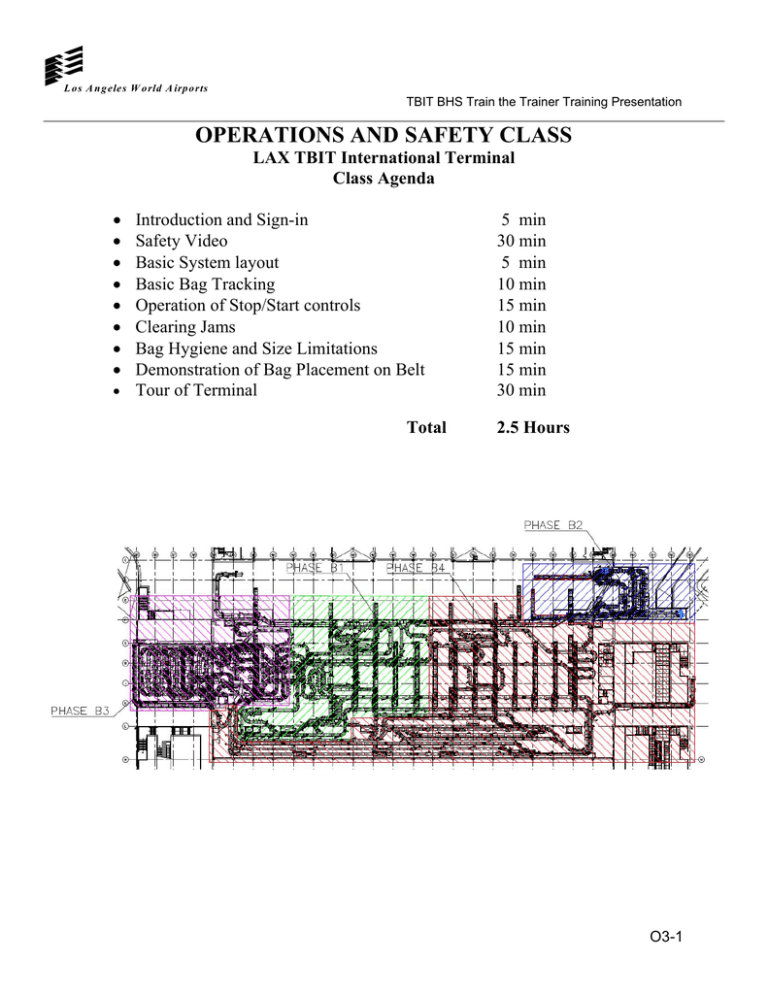
L o s A n g eles W o rld A irp o rts TBIT BHS Train the Trainer Training Presentation OPERATIONS AND SAFETY CLASS LAX TBIT International Terminal Class Agenda • • • • • • • • Introduction and Sign-in Safety Video Basic System layout Basic Bag Tracking Operation of Stop/Start controls Clearing Jams Bag Hygiene and Size Limitations Demonstration of Bag Placement on Belt • Tour of Terminal Total 5 min 30 min 5 min 10 min 15 min 10 min 15 min 15 min 30 min 2.5 Hours O3-1 L o s A n g eles W o rld A irp o rts TBIT BHS Train the Trainer Training Presentation O3-2 L o s A n g eles W o rld A irp o rts TBIT BHS Train the Trainer Training Presentation 3 Baggage Weight & Size Limitations 3.1 Capacities and Usage 3.1.1 Baggage Types The conveyor system is designed to handle baggage types as follows: ● Normal: Items which can be processed by the equipment without special handling, including golf bags and duffel bags. ● Fragile: Items which, when in tote trays, can be processed as normal baggage including garment bags, hat boxes, bowling balls, shipping bags, etc. ● Oddsize: Items which exceed the size and weight limits listed cannot be handled by the equipment and must be manually transported. The system is designed to accommodate a wide range of baggage materials including paper, cardboard, cloth, canvas, plastic, leather, wood, metals, etc. in both dry and wet condition and with or without wrapping, ties, wheels, and straps. Items with straps and/or wheels are meant to be transported with the wheels up off the conveyor and the straps trailing. Always start the conveyor BEFORE loading any baggage. If a conveyor is loaded before starting, the motor may overload. O3-3 L o s A n g eles W o rld A irp o rts TBIT BHS Train the Trainer Training Presentation 3.2 Physical Characteristics The following defines the physical characteristics of baggage used in the design of this system. Normal Physical Characteristics for Ticket Counter & Curb Side Length (in.) Max/Min 54/6 Width (in.) Max/Min 33/3 Height (in.) Max/Min 25/3 Weight (Lbs.) Max/Min 120/1 NOTE: This equipment is designed to convey NORMAL baggage checked by airline passengers. Oversize Physical Characteristics Length (in.) Max/Min 156/6 Width (in.) Max/Min 50/3 Height (in.) Max/Min 34/3 Weight (Lbs.) Max/Min 150/1 NOTE: This equipment is designed to convey OVERSIZE baggage checked by airline passengers. Luggage which is fragile, oddsize, or has exposed wheels or ball casters, are recommended NOT to be transported on standard baggage conveyors. These items should be transported either in a tote tray or by manual means. Luggage which does not have at least one flat conveyable surface (baby carriages, soft bags, etc.) should be transported in a tote tray. Live animals or birds are NOT recommended to be transported on standard baggage conveyors. O3-4 L o s A n g eles W o rld A irp o rts TBIT BHS Train the Trainer Training Presentation 3.3 Electrical Components 3.3.1 Pushbutton Stations Pushbutton stations in the public view are flush mounted with a stainless steel cover plate. Emergency Stop Pushbuttons are “maintained contact, push to stop, pull to reset, illuminated, mushroom head” type. Selector Switches are key operated, where required. Pilot/Indicator Lights are “push-to-test, transformer” type. Lens colors vary, depending on their applications within the system. Photoelectric LED type controls are mounted on structural members attached to the machines. Relays and Time Delay Relays are rated for their specific application. 3.3.2 3.3.2.1 Electrical Component Functions Overheight Detection Overheight photocells are provided at every input to the system to detect bags that are too high to clear the lowest downstream obstruction for all possible routes. These photocells are set at 25-inches above the conveyor. As soon as the beam to the photocell is interrupted, the conveyor will stop. The overheight pushbutton and overheight indicator lamp will illuminate. A reset pushbutton has been provided at the overlength position to restart the conveyor after the overheight bag has been removed from the photocell. 3.3.2.2 Overlength Detection Overlength photocells are installed at every baggage input to the system to detect bags that are too long. The overlength measurement circuit is programmed to stop the conveyor if a preset bag length is exceeded. A reset pushbutton has been provided at the overlength position to restart the conveyor after the overlength bag has been removed from the photocell. 3.3.2.3 Cascade Stop Cascade stop photocells are provided within 6-inches (152 mm) of the discharge ends of all conveyors to stop the conveyor whenever the downstream conveyor is stopped and a bag passes the photocell. These photocells are located 1.5-inches (38 mm) O3-5 L o s A n g eles W o rld A irp o rts TBIT BHS Train the Trainer Training Presentation above the conveyor. As soon as the beam to the photocell is cleared, the conveyor will restart. 3.3.2.4 Jam Detection Jam detection photocells are provided on the discharge ends of all conveyors before power turns, incline conveyors, merges, and all other potential jam areas. When a jam photocell is blocked for a pre-set period of time (typically six seconds), the conveyor with the jam, and the conveyor immediately downstream will stop. The jam indicator lamp will illuminate on the MCP and audible and visible alarms will activate. The light on the jam reset push button will be illuminated. 3.3.2.5 Merge and Priority Control Merge photocells are provided at merges to perform jam detection, head end sensing, and priority control functions. See the Electrical Control Sequence of Operation for more details. 3.3.2.6 Auto-Stop Upstream sections of transport conveyor not specifically controlled by START/STOP switches are provided with auto-stop photocells. If an auto-stop photocell does not sense a bag for an adjustable period of time, the conveyor section will stop. To restart the system, reset the auto-stop timer and hold until the conveyor restarts. 3.3.2.7 Auto-Start Upstream sections of transport conveyor not specifically controlled by START/STOP switches are provided with auto-start photocells. When the auto-start pushbutton is pressed, start-up warning alarms will sound and the conveyors will restart. 3.3.2.8 Start-Up Warning Audible start-up warning alarms are provided on the motor control panels corresponding to subsystems. Alarms and beacons activate for an adjustable period of time prior to the startup of the conveyor subsystem. 3.3.2.9 Fault Warning Alarm An audible alarm is provided on the Control Cabinets controlling each subsystem. Whenever a fault causes a section of conveyor to stop or prevents it from starting, an alarm and one of the following indicator lights will illuminate. 3.3.2.10 Alarm Silence An Alarm Silence momentary contact pushbutton is provided on the door of the Control Cabinet which silences the audible alarm when pressed. Multiple faults will always sound the associated fault warning alarm, even if a previous fault has not been cleared and a new fault occurs. Do not extinguish the illuminated fault indicator until the fault has been corrected. O3-6 L o s A n g eles W o rld A irp o rts TBIT BHS Train the Trainer Training Presentation 3.3.2.11 Emergency Stop Emergency stop pushbuttons are located as indicated on the Electrical Drawings in Chapter M12. Additional pushbuttons are installed to ensure that operating and maintenance personnel can easily and quickly reach an emergency stop pushbutton from anywhere in the system. When an emergency stop pushbutton is pressed, all conveyors in the subsystem stop and the lights in both the head of the pushbutton and the emergency stop fault light will illuminate. When the emergency stop pushbutton is reset (pulled out), the light in the head of the pushbutton will extinguish. When the normal start switch for the conveyor is pushed, the start-up warning alarms will sound and all conveyors in the subsystem will start. 3.4 Abbreviations and Symbols The following table lists, in alphabetical order, the acronyms and the definition/meaning used in subsequent sections of this document. Table 1 Acronyms Acronym Definition ATO Airport ticket office ATR Automatic Tag Reader BAS Bag Advance Switch BHS Baggage Handling System CB Clear Bag Line CD Claim Device CPU Central Processing Unit CS Control Station CS(X-NN) Curb Side conveyor, X=sub system number, NN=conveyor number DPB Dispatch Push Button EC Encode Console EDS Explosive Detection System EPB Emergency stop push button ETD Explosive Trace Detection GDM Graphics Display Monitor HMI Human Machine Interface HSD High Speed Diverter IATA International Air Transport Association IB In bound MCP Motor Control Panel ME Manual Encode O3-7 L o s A n g eles W o rld A irp o rts TBIT BHS Train the Trainer Training Presentation Acronym Definition MEC Manual Encode Console ML Main Line MU Make-up Unit O&M Operations and Maintenance OS Odd Size baggage conveyor OSIB Odd Size Inbound PB Push Button PBS Push Button Stop PE Photo-Eye/photocell PLC Programmable Logic Controller PM Preventive Maintenance SB(X_NN) Suspect Bag Line SC Sortation Controller SG Scan Gun SPB Start Push Button SS(X_NN) Security Screening Line SSW Selector switch TC(X_NN) Ticket counter conveyor TX Transfer conveyor 3.4.1 Glossary The following table presents the terminology encountered in subsequent sections of this document along with the explicit definition of the term as it is used. Table 2 Glossary Term Definition Baggage Any item placed on the baggage handling system conveyor with an attached a bag tag, i.e. IATA, 10 digit flight and 4 digit pier. Hard jam The time when bags for a flight are to be identified, processed, and tracked as late. Close out time is computed as the flight departure time minus a predetermined number of minutes. The predetermined number of minutes is an operator controlled configurable parameter, defined as the closeout period. The closeout time parameter is configurable per flight. Late bag If a bag that should have been diverted towards the ETD room is detected by either or both of the redundant photocells on SS, and/or has not been detected by either or both of the redundant photocells on SB, that bag has failed to divert to SB. This moment the conveyors SS, CB and SB will stop for Fail Safe purpose. Missing Bag Jam A sort device is full when the discharge end photocell is blocked for a period of time. No-read A bag seen at a barcode scanner array or a manual encode station after the flights close out time but before its departure time. O3-8 L o s A n g eles W o rld A irp o rts TBIT BHS Train the Trainer Training Presentation Term Definition Normal Baggage The time when bags for a flight are to be identified, processed, and tracked as locked out. A flight’s locked out time starts from its departure time plus preconfigured minutes and continues up to the System End-of-Day. Odd size Baggage A missing bag jam occurs when three consecutive bags are sensed at a conveyor head end photocell and are not detected at the next downstream photocell within a predetermined time period. Out-of-Gauge Baggage Due to Overload Trip (MOL) O3-9


