Supplemental Correction Sheet for Methane
advertisement
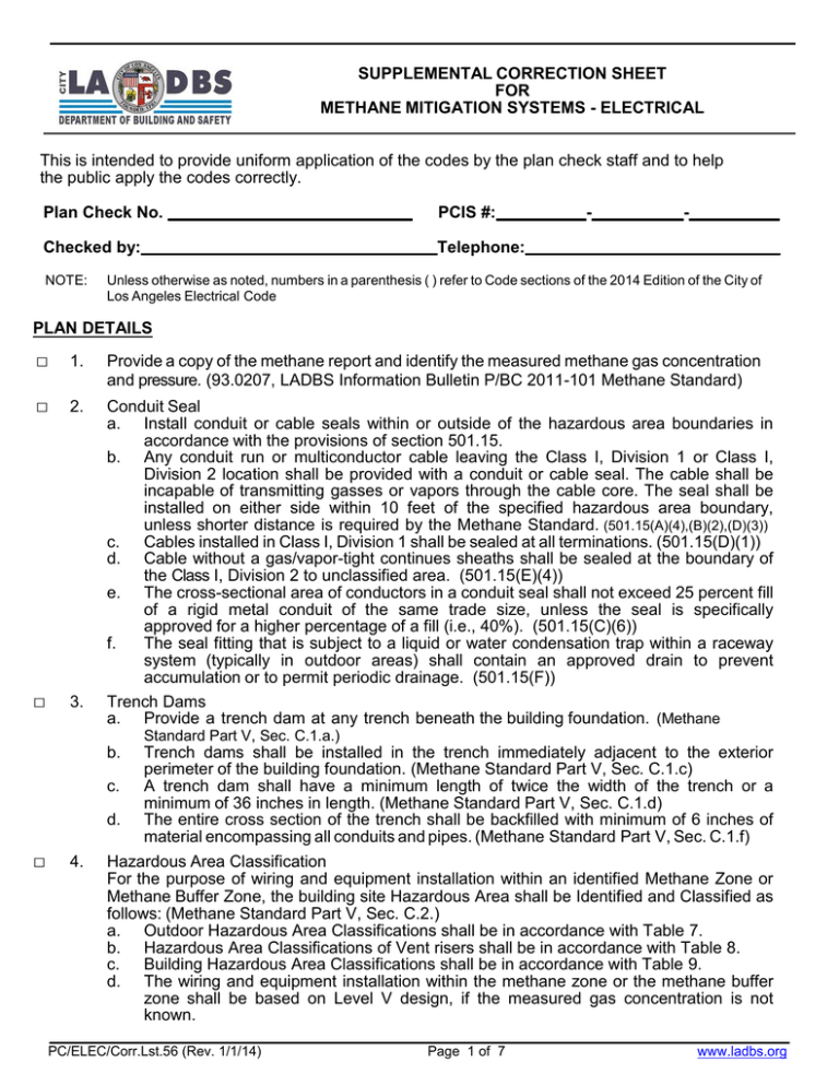
SUPPLEMENTAL CORRECTION SHEET FOR METHANE MITIGATION SYSTEMS - ELECTRICAL This is intended to provide uniform application of the codes by the plan check staff and to help the public apply the codes correctly. Plan Check No. PCIS #: Checked by: Telephone: NOTE: - - Unless otherwise as noted, numbers in a parenthesis ( ) refer to Code sections of the 2014 Edition of the City of Los Angeles Electrical Code PLAN DETAILS □ 1. Provide a copy of the methane report and identify the measured methane gas concentration and pressure. (93.0207, LADBS Information Bulletin P/BC 2011-101 Methane Standard) □ 2. □ 3. Conduit Seal a. Install conduit or cable seals within or outside of the hazardous area boundaries in accordance with the provisions of section 501.15. b. Any conduit run or multiconductor cable leaving the Class I, Division 1 or Class I, Division 2 location shall be provided with a conduit or cable seal. The cable shall be incapable of transmitting gasses or vapors through the cable core. The seal shall be installed on either side within 10 feet of the specified hazardous area boundary, unless shorter distance is required by the Methane Standard. (501.15(A)(4),(B)(2),(D)(3)) c. Cables installed in Class I, Division 1 shall be sealed at all terminations. (501.15(D)(1)) d. Cable without a gas/vapor-tight continues sheaths shall be sealed at the boundary of the Class I, Division 2 to unclassified area. (501.15(E)(4)) e. The cross-sectional area of conductors in a conduit seal shall not exceed 25 percent fill of a rigid metal conduit of the same trade size, unless the seal is specifically approved for a higher percentage of a fill (i.e., 40%). (501.15(C)(6)) f. The seal fitting that is subject to a liquid or water condensation trap within a raceway system (typically in outdoor areas) shall contain an approved drain to prevent accumulation or to permit periodic drainage. (501.15(F)) Trench Dams a. Provide a trench dam at any trench beneath the building foundation. (Methane Standard Part V, Sec. C.1.a.) b. □ 4. Trench dams shall be installed in the trench immediately adjacent to the exterior perimeter of the building foundation. (Methane Standard Part V, Sec. C.1.c) c. A trench dam shall have a minimum length of twice the width of the trench or a minimum of 36 inches in length. (Methane Standard Part V, Sec. C.1.d) d. The entire cross section of the trench shall be backfilled with minimum of 6 inches of material encompassing all conduits and pipes. (Methane Standard Part V, Sec. C.1.f) Hazardous Area Classification For the purpose of wiring and equipment installation within an identified Methane Zone or Methane Buffer Zone, the building site Hazardous Area shall be Identified and Classified as follows: (Methane Standard Part V, Sec. C.2.) a. Outdoor Hazardous Area Classifications shall be in accordance with Table 7. b. Hazardous Area Classifications of Vent risers shall be in accordance with Table 8. c. Building Hazardous Area Classifications shall be in accordance with Table 9. d. The wiring and equipment installation within the methane zone or the methane buffer zone shall be based on Level V design, if the measured gas concentration is not known. PC/ELEC/Corr.Lst.56 (Rev. 1/1/14) Page 1 of 7 www.ladbs.org e. □ 5. □ 6. The wiring and equipment installation within the methane zone or the methane buffer zone shall be based on soil gas pressure more than 2 inches of water column, if the measured gas pressure is not known. Wiring Method The wiring and equipment installed within an identified Methane Zone (or Methane Buffer Zone) including hazardous areas shall comply with the following requirements: a. Wiring method and equipment installed within or outside of a Hazardous Area boundary shall be in accordance with the provisions of the Los Angeles Electrical code. (500, 93.515.17, 93.515.18) b. Wiring method in underground installations shall be of materials suitable for the exposed corrosive environment. (300.6) c. Provide a pull box fitted with a breather suitable for class I, Group D locations when the Design Methane Pressure is greater than 6” of water. (Methane Standard Part V, Sec. C.3.a) i. The breather shall be located on the side of the enclosure within 2 inches from the top of the pull box. ii The breather shall have minimum dimensions of 1.5 inches long, and 15/16 inch in diameter. d. Provide a pull box fitted with louvers installed in a non classified area as follows: (Methane Standard Part V, Sec. C.3.a.iii) i. The louvered openings shall be within 2 inches from the top of the box. ii. The minimum total enclosure ventilation opening shall be 1.41 square inches. e. All outdoor equipment with open bottoms installed on grade or a finished floor shall be mounted on a minimum 2 inch thick concrete pad that is installed on top of a 30mil High Density Polyethylene (HDPE) or equivalent impervious membrane. All penetrations through the membrane shall be sealed against gas migration with approved material. (Methane Standard Part V, Sec. C.3.b) f. The DWP pull box and the Service pull box shall be installed as follows: i. The DWP pull box shall be located outside of the building. ii. The wiring system from the DWP pull box to a service pull box shall be supplemented with a code approved seal fittings. iii. The service pull box shall be at a location either outside of a building or structure or inside nearest to the point of entrance of the service conductors. iv. The conduit or cable seal fittings shall be installed at the point of service entrance conductor emergence into the service pull box or within 18 inches from the service pull box. g. Polyvinyl chloride conduits (PVC) are not permitted to be installed in Class I Division 2 Hazardous Area, unless it is installed in accordance with provisions of Class I Division 1 wiring method. (501.10(B)) h. PVC installed in a Class I Division 1 Hazardous Area shall be encased in concrete envelop that is a minimum of 2 inches thick. There shall be no less than 24 inches of cover measured from the top of the PVC or RTRC conduit to the grade. (501.10(A)(1)(a)Exception) i. In Class I Division 1 Hazardous Area, the last 24 inches of the underground run of PVC or RTRC before emergence from a grade or to the above ground installed raceways shall be a threaded rigid metal conduit or threaded steel intermediate conduit. (501.10(A)(1)(a)Exception) j. Provide an equipment grounding conductor for any PVC or RTRC installed in Hazardous Classified area. (501.10(A)(1)(a)Exception, 501.30) Manholes and Other Underground Electric Enclosures Intended for Personnel Entry (here in referred to as “Underground Enclosures” ) (Methane Standard Part V, Sec. C.4) a. Underground Enclosures such as vaults that are more than 4 feet in depth and width shall be submitted to building plan check for Methane mitigation and other structural approval. (LADBS Information Bulletin P/BC 2011-017, Concrete Vaults) PC/ELEC/Corr.Lst.56 (Rev. 1/1/14) Page 2 of 7 www.ladbs.org b. c. d. Vent System: i. Non explosion proof Underground Enclosures installed in Hazardous Classified Area intended for personnel entry shall be ventilated per detail 15 of the methane standard. (Methane Standard Part V, Sec. C.4.a.i) ii. Purged or Pressurized protected (i.e., mechanically ventilated) Underground Enclosures intended for personnel entry shall be provided with a minimum of 24 hours of back-up power and a main visual and audible power failure alarm at a readily accessible location. (Methane Standard Part V, Sec. C.4.a.ii) Enclosure Exterior i. Joints between pre-cast sections of Underground Enclosures shall be sealed with an approved (waterproof epoxy) compound (extending 2 inches beyond the rims of the joint) as indicated in detail 15. (Methane Standard Part V, Sec.C.4.b.i) ii. Underground Enclosure entree cover and its restraint system shall be per detail 15 of the Methane Standard. (Methane Standard Part V, Sec. C.4.b.ii) iii. Soil gas under the Underground Enclosure shall be vented according to provisions of detail 15. (Methane Standard Part V, Sec. C.4.b.iii) Enclosure Interior i. All wiring terminations, equipment and insulating materials used inside the vault shall be suitable for wet location. (Methane Standard Part V, Sec. C.4.c.i) ii. Conduits entering or leaving the vault shall be sealed with an approved duct seal. The duct seal shall have a depth of not less than the diameter of the conduit. (Methane Standard Part V, Sec. C.4.c.ii) iii. The wiring method in Purged or Pressurized (i.e., mechanically ventilated) protected Underground Enclosures shall be in accordance with NFPA 496-2003 (500.4(B)) □ 7. Grounding (Methane Standard Part V, Sec. C.3.d.) a. Electrical Systems shall be grounded using a t le a st one of the following grounding electrode systems: (Methane Standard Part V, Sec. C.3.d.i) i. Metal Underground Water Pipe, ii. Ground Ring, or iii. Made and Other (Approved) Electrodes. b. Modified or altered approved grounding electrode systems shall be designed based on site investigation of the soil electrical resistivity as specified below: (Methane Standard Part V, Sec. C.3.d.ii) i. Soil Electrical Resistance (1) The soil resistivity shall be measured by the four-point method as described in IEEE Standard 81, 1983-edition. (2) The soil resistivity measurement shall take into account the geological features of the soil as determined by the engineer. Whenever driven ground rods are to be used, the measurement shall correlate with the installed effective depth of the ground electrodes. (3) The engineering analysis shall take into account the expected deviations in soil temperature, moisture and gas or soluble chemical contents. (4) The soil resistivity measurement shall be based on embedment of the electrodes below the permanent moisture level, when such installation is possible. ii. Measurement (1) For installations of multiple rod and pipe or plate electrodes in a single row, measurement shall be in a straight line at the location were these electrodes are intended to be installed. (2) For installations of ground rings (circular or square), grids, grid beds, radial, etc., the area that is to be used for grounding shall be divided into rows. Each row shall be equally spaced apart. The measurement shall be started at the corner of the first row and then continued through each pre determined point in the row. This measurement is then repeated through the last row. The measurement shall be performed until all pre determined points are covered. PC/ELEC/Corr.Lst.56 (Rev. 1/1/14) Page 3 of 7 www.ladbs.org (3) (4) These measurements shall account for the water table, soil layers, corrosion, etc. when applicable. Indicate if the interconnecting conductor between ground rods and the grounding electrode system is bare or an insulated copper conductor. (93.0207) □ 8. Any conduit, raceway or cable penetration through the membrane shall be adequately sealed against methane migration. Provide details on the plan. (Methane Standard Part V, Sec. A.3.b.i) □ 9. Mechanical Ventilation System (Methane Standard Part V, Sec. B.2.b.iii) a. Mechanical Ventilation systems shall be activated by the Gas Detection and (Methane) Control Panel, at 10% LEL (5,000 p.p.m.v.). b. Continuous or Scheduled Start-up Mechanical Ventilation (no gas detectors and pressure sensors are provided) shall be provided with 24 hours of (legally required) back-up power. □ 10. Alarm System (Methane Standard Part V, Sec. B.2.c.) a. The Alarm System shall consist of audible or visual signals to notify occupants of significant levels of methane intrusion into the building. b. Alarm systems shall be designed with the Sequence of Operation as shown in Table 5 of the Methane standard. □ 11. Gas Detection System (Methane Standard Part IV, C.5, and Part V, Sec. B.3) a. Provide the single-line diagram and specification sheets for the proposed gas detection system. (93.0207) b. Provide pressure sensors as required by Table 1A & 1B. c. Provide gas detectors as indicated in Table 6. The detectors shall be installed with respect to airflow in rooms, location of probable gas leaks (i.e., elevator pits, building column, cold water pipe rise from or into below the building membrane) and the recommendations of the manufacturer. (Methane Standard Part V, B.2.a) d. Install a gas detection and alarm system within the building lowest level as required by Table 1A & 1B. e. Single station gas detectors in lieu of gas detection system may be installed within lowest level of each single family dwelling unit. The single station gas detector shall be provided with a built-in battery backup power capable of providing minimum of 24 hours in standby mode and 5 minutes in the alarm mode. (Methane Standard Part V, Sec.B.3.b) f. The pressure sensor below the Impervious Membrane can be used in lieu of the required Gas Detection System in a single family dwelling unit when they are not required by Table 1A or 1B. (Methane Standard Part V, B.5.a) g. The Gas Detection System shall consist of gas detectors, pressure sensors and the gas detection control panel. The detectors, sensors, control unit and other associated parts shall comply with the following: i. Pressure Sensors (1) Probes for pressure sensors shall be installed below the impervious membrane at a minimum rate of one pressure sensor probe per 20,000 square feet of building footprint or fraction thereof. (2) Pressure sensor probes shall be installed within the gravel blanket a minimum of 2 inches below the impervious membrane. (3) Each building shall be equipped with a minimum of two pressure sensors measuring pressure below the impervious membrane. (4) Pressure sensor devices shall be located to accurately measure gas pressure below the Impervious Membrane relative to the ambient pressure of lowest occupied spaces. (5) Methane vent risers and horizontal vent pipes shall not be used to run wires to the pressure sensors. Install approved pressure sensors below the membrane. PC/ELEC/Corr.Lst.56 (Rev. 1/1/14) Page 4 of 7 www.ladbs.org ii. iii. iv v. Gas Detectors in Vent Risers (1) The detector shall be fitted within the vent pipe so that no gas may leak through the fittings. The associated wiring and associated raceways shall be as follows: (1) Mounted to a secure surface independent of detectors and their associated transmitter. (2) Protected from any physical damage. Gas Detection and Pressure Sensor Control Panel (1) The Gas Detection and Pressure Sensor Control Panel(s) shall consist of devices that receive signals from the gas detectors and pressure sensors in vent risers (initiating devices) and send signals to the alarm (notification) or ventilation start system(s). (2) The control panel shall provide (Legally Required) back-up power, to operate all loads supplied from the control unit. (I.e., gas detectors, pressure sensors, annunciator, and associated components) under full load condition for a minimum of 24 hours in the standby mode, plus 5 minutes for alarm. (3) Each control panel shall contain an annunciator to indicate each trouble condition, including low and high alarm conditions. (4) The mechanical extraction system shall not override the building fire alarm, smoke control, and ventilation systems. (5) The control panel shall recognize alarm conditions, then activate required audible devices, visual devices, and vent equipment. (6) The control panel shall supervise and indicate a fault or trouble condition with the following circuits (as applicable): Main supply circuits, Rechargeable battery circuits, Initiating device circuits, Alarm device circuits, Supplementary or auxiliary signaling circuits, and Signaling line circuits. (7) The Gas Detection and Pressure Sensor Control Panel shall activate devices as described in Table 9 of the Methane Standard. Provide the control unit wiring diagram. This diagram shall identify the connection points and components needed to complete the wiring of methane detection system. (8) Indicate how the control unit will initiate a trouble alarm at the panel in the event of power loss to the unit. (9) The field wiring from the control unit to any device shall electrically be supervised against any single open or ground. Such failure mode shall be indicated by an audible alarm at the control unit. (10) Control units shall contain an annunciator. Gas Extraction Powered Devices Gas Extraction Powered Devices shall be activated when signaled by the Gas Detection and Pressure Sensor Control Panel per table 1A and 1B of the Methane Standard. CALCULATIONS □ 1. □ 2. □ 3. Provide a copy of Ground Electrical Resistance Test report including all details as required per standard for alternate grounding system. (Methane Standard Part V. Sec. C.3.d.ii) The design and measured ground resistance to earth for alternate ground system shall not exceed 25 ohms for low voltage system and 5 ohms for high voltage system. Provide the ground resistance analysis for the proposed alternate grounding system. (Methane Standard Part V, Sec. C.3.d.ii) Provide the worst case voltage drop calculation for the initiating, indicating and signaling (as applicable) circuits. (93.0207) PC/ELEC/Corr.Lst.56 (Rev. 1/1/14) Page 5 of 7 www.ladbs.org □ 4. □ 5. □ 6. □ 7. Provide the end of line resistor calculation for non addressable methane detection and sensing circuits. (93.0207) Provide the load calculation and the size of the legally required backup power for the gas detection control panel. (701, Methane Standard Part V I, Sec. B. 3.b) Provide the load calculation and the size of the legally required backup power for the Continuous or Scheduled Start-up Mechanical Ventilation. (701, Methane Standard Part V, Sec. B.2.b.iii) The total time delay for the legally required backup source shall not exceed 60 seconds from the time of loss of power. (701.11) NOTES ON PLANS □ □ □ 1. 2. 3. □ 4. □ 5. □ 6. □ □ 7. 8. □ 9. □ 10. □ 11. □ 12. □ 13. □ 14. □ 15. □ 16. □ 17. □ 18. □ 19. □ 20. □ 21. The site methane level is __ and the site measured pressure is ___inches of water column. The methane site investigation report by ____________________, date__________ . All devices, control unit(s) and wiring shall be listed by a recognized testing laboratory and suitable for the intended use in the classified hazardous or corrosive environments when installed in such areas. The associated wiring and associated raceways shall be: a. Mounted to a secure surface independent of detectors and their associated transmitter. b. Protected from any physical damage. The conduit seal shall be filled with an approved sealing compound. The compound shall have a melting point of more than 200°F. The conduit seal compound shall have minimum thickness not less than the trade size of the conduit, but in no case shall be smaller than 5/8 inches. No splicing or taps shall be made within a conduit seal. Trench dam shall be made of the following: a. Betonite concrete slurry – consist of 4% type II concrete and 2% powdered betonite. (Methane Standard Part V, Sec. C.1.e), or b. Soil compacted to a minimum 90 percent of the maximum dry density of the fill material. Wiring material shall be suitable for the corrosion exposure. Field applied corrosion protective coatings are not acceptable. The concrete anchor shall have a minimum strength of 2,500 psi. (Methane Standard Detail 15) Prior to concrete encasement of any vent pipe, use approved PVC cement and epoxy coating to seal the termination joints. The vent pipes and cavity around the underground enclosure that is intended for personnel entry shall be backfilled with approved material and compacted to at least 90% compaction. The ground electrodes and interconnecting conductors shall be installed in the backfill around new building foundations only after the soil has been compacted to 90% relative compaction. The electrode system shall be installed in an area either below or at least 3 feet away from any impermeable membrane. The grounding electrode conductor shall not be installed in gravel beds intended for a drainage purpose. Audible alarms shall be at least 15-db above ambient noise level in all areas subject to methane gas intrusion. (Methane Standard Part V, Sec. B.2.c) Visual alarms shall be capable of producing minimum of 15 candelas. (Methane Standard V.B.2.c) All methane alarms shall produce an audible signal distinctively different that of a fire alarm system. (Methane Standard Part V, Sec. B.2.c) Signs shall be posted adjacent to each alarm indicating, “Methane Alarm – Evacuate Building Call 911.” (Methane Standard Detail 11) The pressure sensors shall receive power, report gas pressures, and be calibrated by signals from the Gas Detection and Pressure Sensor Control Panel. The control panel shall indicate a fault or trouble condition by a visual alarm at the control unit. (Methane Standard Part V, Sec. B.3.c.ii) PC/ELEC/Corr.Lst.56 (Rev. 1/1/14) Page 6 of 7 www.ladbs.org □ □ □ □ □ 22. The gas detectors and associated wiring shall be immune to radio frequency and infrared remote-transmitters frequency interference. (Methane Standard Part V,Sec. B.1.b.i) 23. The gas detection and pressure sensor control panel(s) shall be compatible with methane detection or initiation devices. 24. The detectors and the associated wiring material shall be protected from any physical damage. 25. The expanded metal screen of an elevator pit detector shall not inhibit the operation of the detector. 26. The control units shall be capable to recognize an alarm condition and activate required audible and visual devices. (Methane Standard Part V, Sec. B.3.c.i) PC/ELEC/Corr.Lst.56 (Rev. 1/1/14) Page 7 of 7 www.ladbs.org
