EST Catalog u Strobes, Horns, Bells, Chimes
Field Configurable
Ceiling Strobes
Genesis Series
One or more patents pending.
7125-1657:
0219
S5389
Overview
Standard Features
Genesis life
������������������������������������������������������
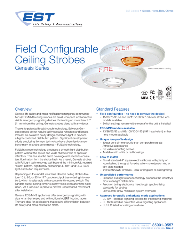
safety and mass notification/emergency communications (ECS/MNS) ceiling strobes are small, compact, and attractive
visible emergency signaling devices. Protruding no more than 1.6”
(41 mm) from the ceiling, Genesis strobes blend with any decor.
• Field configurable – no need to remove the device!
– 15/30/75/95 cd and 95/115/150/177 cd clear strobe lens models available
– Switch settings remain visible even after the unit is installed
Thanks to patented breakthrough technology, Edwards Genesis strobes do not require bulky specular reflectors and lenses.
Instead, an exclusive cavity design conditions light to produce
a highly controlled distribution pattern. Significant development
efforts employing this new technology have given rise to a new
benchmark in strobe performance – FullLight technology.
• ECS/MNS models available
– 13/26/65/82 and 82/100/130/155 (1971 equivalent) amber lens models available
FullLight strobe technology produces a smooth light distribution
pattern without the spikes and voids characteristic of specular
reflectors. This ensures the entire coverage area receives consistent illumination from the strobe flash. As a result, Genesis strobes
with FullLight technology go well beyond the minimum UL-required
“cross” pattern, significantly exceeding UL-1971 and ULC-S526
light distribution requirements.
• Unique low-profile design
– 30 per cent slimmer profile than comparable signals
– Attractive appearance
– No visible mounting screws
– Available with white or red housings
• Easy to install
– Fits all standard 4” square electrical boxes with plenty of
room behind the signal for extra wire – no extension ring or
trim plate needed
– #18 to #12 AWG terminals – ideal for long runs or existing wiring
Depending on the model, clear lens Genesis ceiling strobes feature 15 to 95, or 95 to 177 candela output (see ordering information), which is selectable with a conveniently-located switch. The
candela output setting remains clearly visible even after final installation, yet it is locked in place to prevent unauthorized movement
after installation.
• Unparalleled performance
– Exclusive FullLight strobe technology produces the industry’s
most even light distribution
– Precision timing electronics meet tough synchronizing
standards for strobes
– Low current draw minimizes system overhead
Genesis ECS/MNS appliances offer emergency signaling with
clear or amber lenses and with optional ALERT housing labels.
They are ideal for applications that require differentiation between
life safety and mass notification alerts.
• Approved for public and private mode applications
– UL 1971-listed as signaling devices for the hearing impaired
– UL 1638-listed as protective visual signaling appliances
– UL/ULC listed for ceiling or wall use
Page 1 of 4
85001-0557
D ATA S H E E T
Not to be used for installation purposes. Issue 7
Application
Dimensions
Genesis strobes are UL 1971 or 1638 listed for indoor use. Prevailing
codes require strobes to be used where ambient noise conditions
exceed specified levels, where occupants use hearing protection,
and in areas of public accommodation. Consult with your Authority
Having Jurisdiction for details.
6.8" dia.
(173 mm)
1.0"
(25 mm)
All Genesis strobes exceed UL synchronization requirements
(within 10 milliseconds over a two-hour period) when used with a
synchronization source. Synchronization for multiple strobe lights
in a single field of view is required.
ECS/MNS Applications
Genesis ECS/MNS appliances bring the same high-performance life
safety features and unobtrusive design to mass notification applications. Available as standard units with clear or amber lenses with
optional ALERT markings, thy are ideal for applications that require
differentiation between life safety and ECS/MNS signals. Units are
also available (special order) with red, blue or green lenses.
0.60"(15 mm)
Light output (effective cd)
Percent of UL rating versus angle
Percentage of rated output
120 110 100 90
80
70
60
50
40
30
20
10
0
10
20
30
40
50
60
70
80
90 100 110 120
75°
-75°
Installation
All models are intended for indoor applications only. Strobes
mount to any flush North-American 4” square electrical box, 21/8”
(54 mm) deep.
Genesis ceiling strobes simply unlatch and twist to open. This
gains access to mounting screws and the selectable candela
switch. The shallow depth of Genesis devices leaves ample room
behind the signal for extra wiring. Once installed with the cover in
place, no mounting screws are visible.
90°
60°
-60°
45°
-45°
30°
-30°
-15°
0°
15°
Angle
Horizontal and vertical outputs reflect the same pattern.
Field Configuration
75
95
Candela switch
30
Depending on the model, Genesis ceiling
speaker-strobes have multi-candela output
(see ordering information). The output
setting is changed by simply opening the
device and sliding the switch to the desired
setting. The strobe does not have to be
removed to change the output setting.
The setting remains visible through a small
window on the front of the device after the
cover is closed.
15
Indicator
Wiring
Field wiring terminals accommodate #18 to #12 AWG (0.75 mm²
to 2.5 mm²) wiring. Strobes are interconnected with a single pair of
wires as shown below.
Page 2 of 4
WARNING: These devices will not operate without electrical power. As fires frequently
cause power interruptions, we suggest you discuss further safeguards with your
local fire protection specialist.
85001-0557
D ATA S H E E T
Not to be used for installation purposes. Issue 7
Current Draw
Light output switch settings for UL 1971 listed models are selectable by numeric candela value.
ECS/MNS appliances are selectable by A, B, C, or D designations.
UL
Rating
16 Vdc
16 Vfwr
Light output setting, standard models
“15” or ”D”
“30” or ”C”
“75” or ”B”
“95” or ”A”
RMS
RMS
RMS
RMS
109
151
281
318
131
194
379
437
Light output setting, high output models
“95” or ”D”
“115” or ”C”
“150” or ”B”
“177” or ”A”
RMS
RMS
RMS
RMS
330
392
502
565
432
518
643
693
Typical
Current
16 Vdc
20 Vdc
24 Vdc
33 Vdc
16 Vfwr
20 Vfwr
24 Vfwr
33 Vfwr
Light output setting, standard models
“15” or ”D”
“30” or ”C”
“75” or ”B”
“95” or ”A”
RMS
RMS
RMS
RMS
94
140
273
325
74
108
205
244
63
90
168
194
48
70
124
139
126
187
368
403
108
156
281
333
97
139
240
270
89
119
197
214
Light output setting, high output models
“95” or ”D”
“115” or ”C”
“150” or ”B”
“177” or ”A”
RMS
RMS
RMS
RMS
333
392
499
551
259
303
378
429
212
245
306
342
155
180
211
236
484
570
673
724
380
438
537
604
318
361
434
484
245
269
308
338
Current values are shown in mA.
Specifications
Housing
Lens
Mounting
Wire Connections
Operating Voltage
Operating environment
Agency listings/approvals
Strobe output rating
Strobe operating voltage
Strobe flash rate
Synchronization
Synchronization Sources
Page 3 of 4
Textured UV stabilized, color impregnated engineered plastic. Exceeds 94V-0 UL flammability rating. Red and white models
available.
Optical grade polycarbonate (clear).
Flush mount to North American 4-inch square electrical box, 2-1/8 (54 mm) inches deep. No extension ring required.
Suitable for indoor wall or ceiling applications.
Screw terminals: #18 to #12 AWG (0.75 mm² to 2.5 mm²) wire size.
Regulated 16 to 33 Vdc, 16 to 33 Vfwr.
Indoor: 32-120° F (0-49° C) ambient temperature; 0-93% relative humidity.
Meets or exceeds year 2004 UL requirements for standards UL1638 and UL1971 and Canadian requirements for
standards CAN/ULC S526-02 and CAN/ULC S524-01. All models comply with ADA Code of Federal Regulation Chapter
28 Part 36 Final Rule. CSFM, MEA, FM.
UL 1971, UL 1638, ULC S526: selectable 15/30/75/95 cd (GC-VM) and 95/115/150/177 cd (GC-VMH)
GC-VM series strobes: non-coded, filtered 16-33 Vdc
or unfiltered 16-33 Vdc FWR.
GC-VM series strobes: one flash per second synchronized with optional G1M Genesis Signal Master indefinitely within 10
milliseconds. Temporal setting (private mode only): synchronized to temporal output of Genesis audible signals on same
circuit.
Meets or exceeds UL 1971 requirements. Maximum allowed resistance between any two devices is 20 Ohms. Refer
to specifications for the synchronization control module, this strobe, and the control panel to determine allowed wire
resistance.
SIGA-CC1S, SIGA-MCC1S, SIGA-CC2A, SIGA-MCC2A, G1M-RM
BPS6A, BPS10A, APS6A, APS10A, iO64, iO500, Fireshield Plus 3, 5 and 10 zone.
Add G1M for G1-CVM &G1-HDVM devices only.
85001-0557
D ATA S H E E T
Not to be used for installation purposes. Issue 7
Ordering Information
Light output switch settings for UL 1971 listed models are selectable by numeric
candela value.
ECS/MNS appliances are selectable by A, B, C, or D designations.
Contact us...
Email: edwards.fire@fs.utc.com
Web: www.est-fire.com
EST is an EDWARDS brand.
1016 Corporate Park Drive
Mebane, NC 27302
In Canada, contact Chubb Edwards...
Email: inquiries@chubbedwards.com
Web: www.chubbedwards.com
© 2013 UTC Fire & Security Americas
Corporation, Inc. All rights reserved.
Specifications subject to change
without notice. Edwards is part of UTC
Climate, Controls & Security, a unit of
United Technologies Corporation.
Model
Housing
Marking
Lens
Strobe
Ship Wt.
Life safety Appliances (c/w running man icon screen printed on housing)
GC-VM
White
None
Selectable
GCF-VM
White
“FIRE”
15, 30, 75, or 95 cd
GCFR-VM
Red
“FIRE”
Clear
GC-VMH
White
None
Selectable high output
95, 115, 150, or 177 cd
GCF-VMH
White
“FIRE”
ECS/MNS Appliances (no running man icon on housing)
GCWA-VMA
Amber
“Alert”
GCWA-VMC
Clear
Selectable
A, B, C, D
GCWN-VMA
Amber
None
GCWN-VMC
Clear
White
GCWA-VMHA
Amber
“Alert”
GCWA-VMHC
Clear
Selectable high output
A, B, C or D
GCWN-VMHA
Amber
None
GCWN-VMHC
Clear
1.8 lb.
(0.82 kg.)
1.8 lb.
(0.82 kg.)
Units with red, blue or green lenses are available as a special order. Contact customer service for
details.
85001-0557
D ATA S H E E T
Not to be used for installation purposes. Issue 7
06-27-13
Page 4 of 4

