phase master 190e series
advertisement

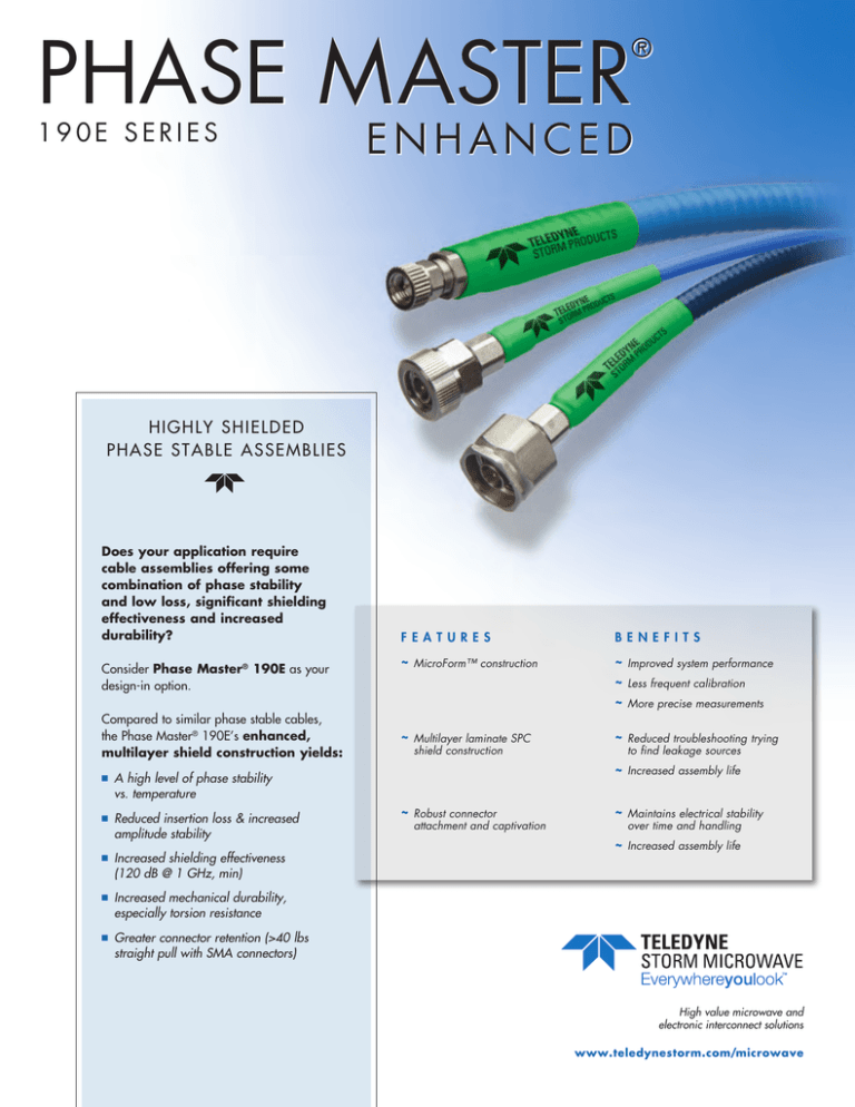
PHASE MASTER ® 190E SERIES ENHANCED HIGH LY S H I ELD ED P HAS E STAB LE AS S EM B LI ES Does your application require cable assemblies offering some combination of phase stability and low loss, significant shielding effectiveness and increased durability? Consider Phase Master® 190E as your design-in option. Compared to similar phase stable cables, the Phase Master® 190E’s enhanced, multilayer shield construction yields: n A high level of phase stability vs. temperature n Reduced insertion loss & increased amplitude stability n Increased shielding effectiveness (120 dB @ 1 GHz, min) n Increased mechanical durability, especially torsion resistance n Greater connector retention (>40 lbs straight pull with SMA connectors) F E A TU R E S B E NE F I TS ~ MicroForm™ construction ~ Improved system performance ~ Less frequent calibration ~ More precise measurements ~ Multilayer laminate SPC shield construction ~ Reduced troubleshooting trying to find leakage sources ~ Increased assembly life ~ Robust connector attachment and captivation ~ Maintains electrical stability over time and handling ~ Increased assembly life High value microwave and electronic interconnect solutions www.teledynestorm.com/microwave p h ase m aster ® E N H A N C E D SPECIFICATIONS PHASE MASTER® 190E Cable Designator 874 875 876 0.199/5.05 0.435 / 11.04 0.349 / 8.86 Operating Frequency (Max, GHz) 26.5 26.5 26.5 Attenuation–Nom @ 2 GHz (dB/ft) 0.112 0.112 0.112 Attenuation–Nom @ 10 GHz (dB/ft) 0.261 0.261 0.261 Attenuation–Nom @ 18 GHz (dB/ft) 0.359 0.359 0.359 Attenuation–Nom @ 26.5 GHz (dB/ft) 0.446 0.446 0.446 700 700 700 <500 from –55 to +85* <500 from –55 to +85* <500 from –55 to +85* –120 –120 –120 1.35 @ 18 GHz 1.40 @ 26.5 GHz 1.35 @ 18 GHz 1.40 @ 26.5 GHz 1.35 @ 18 GHz 1.40 @26.5 GHz 1.38 / 35.05 1 / 25.4 40/18.14 40/18.14 40/18.14 21 64 39 82.4 82.4 82.4 –55 to +125 –55 to +125 –55 to +125 Diameter (in/mm) Power Handling Average Power in Watts @ 1 GHz Phase Stability vs. Temperature (ppm, nom, °C) Shielding Effectiveness–Minimum‡ (dB @ 1 GHz) Typical VSWR (2 straight connectors) 1/25.4 static Min Bend Radius (in/mm) 2/50.8 dynamic Connector Retention up to 18 GHz, straight pull (lbs/kg) Weight (grams/ft) Velocity of Propagation (%) Operating Temperature Range (°C) * <800 up to +125 † ± 90 degree bends around a 4" mandrel ‡ Subject to connector choice Specifications subject to change without notice. CABLE CONSTRUCTION Phase Master ® 190E cable features the proprietary combination of high performance, tape-wrapped PTFE dielectric and helically wrapped SPC foil shield common to all Phase Master ® cables, plus a surrounding laminate of multiple SPC flat wire shields. This enhanced Phase Master ® construction yields not only a high level of phase stability vs. temperature and flexure but significantly increased shielding effectiveness and increased product durability, especially with regard to torsion and connector retention. A B C D E F A Silver-plated (OFHC) copper center conductor E Helically wrapped silver-plated copper foil B Expanded PTFE dielectric F Silver-plated copper braid C Helically wrapped silver-plated copper foil G Extruded blue FEP jacket G D Silver-plated copper braid 630.754.3300 www.teledynestorm.com/microwave n p h ase m aster ® E N H A N C E D Phase Master® ENHANCED – SHIELDING EFFECTIVENESS 150 PM190E 140 PM190E 130 COMPETITOR RF LEAKAGE, dB 120 110 100 COMPETITOR 90 80 70 New Cable Assemblies 60 Cable Assemblies After Simulated Usage 50 40 1 2 3 4 5 6 7 8 9 10 11 12 13 14 15 16 17 18 FREQUENCY (GHz) Phase Master® 190E CABLE – PHASE vs. TEMPERATURE 3000 T Y P I C A L P H A S E S H I F T, P P M 2500 2000 1500 1000 500 0 -500 -1000 -80 -60 -40 -20 0 20 40 60 80 100 120 140 T E M P E R AT U R E , C 630.754.3300 www.teledynestorm.com/microwave n PHASE MASTER H IG H L Y S H IEL D ED PHASE STABLE C A B L E A S S EM B L IES ® 190E SERIES ENHANCED O R D E R I N G I N F O R M A T I O N : Part Number Designation CABLE DESIGNATOR CONNECTOR COMBINATION PART NUMBER 874, 875, 876 ASSEMBLY LENGTH IN INCHES see examples 874 - PM 190E (Unarmored) 875 - PM 190EA (Hard Armored; polyolefin jacket) 876 - PM 190ER (Ruggedized; polyurethane jacket) Examples: 874-0404-048 =Unarmored Phase Master ® 190E, 3.5 mm SP to 3.5 mm SP (assembly operates to 26.5 GHz), 48 inches 876-0606-120 =Ruggedized Phase Master ® 190E, SMA SJ to SMA SJ (assembly operates to 18 GHz), 120 inches CONNECTOR OPERATING FREQUENCY 18 GHz 26.5 GHz P SP SP SJ SP D SJ CS TN N A SM A mm SM 3.5 NM mm mm 3.5 3.5 CONNECTOR COMBINATION PART NUMBERS* SJ 3.5 mm NMD SJ 0505 0405 0507 0105 0506 0305 0205 26.5 GHz 18 GHz * 3.5 mm SP CONNECTOR CODES 0405 0404 0407 0104 0406 0304 0204 3.5 mm SJ 0507 0407 0707 0107 0607 0307 0207 SMA SP 0105 0104 0107 0101 0106 0103 0102 SMA SJ 0506 0406 0607 0106 0606 0306 0206 N SP 0305 0304 0307 0103 0306 0303 0203 TNC SP 0205 0204 0207 0102 0206 0203 0202 SP Straight Plug SJ Straight Jack NMD Ruggedized Test Port Connector Other connector styles available, including #8 Pin and Socket 38999; consult Storm Teledyne Storm Products Microwave Business Unit 10221 Werch Drive Woodridge, Illinois 60517 Tel 630.754.3300 Fax 630.754.3500 Toll Free 888.347.8676 storm_microwave@teledyne.com www.teledynestorm.com/microwave 04/12


