Wave Shield Talking Clock
advertisement
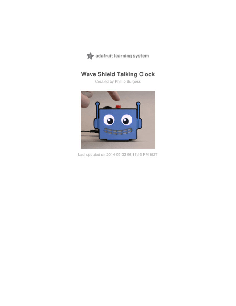
Wave Shield Talking Clock
Created by Phillip Burgess
Last updated on 2014-09-02 06:15:13 PM EDT
Guide Contents
Guide Contents
2
Overview
3
Parts List
3
Dry Run
4
Troubleshooting
4
Arts & Crafts
10
Recording New Voices
15
How the Code Works
19
Save RAM with PROGMEM
19
No Weasels!
20
Power Games
20
Walking while Chewing Gum
22
Dirty Pool
22
© Adafruit Industries
https://learn.adafruit.com/wave-shield-talking-clock
Page 2 of 24
Overview
Here’s a different take on DIY clock projects. Whereas most dwell on visual displays, ours
features Adabot’s friendly face speaking the time.
Best of all, you can make this your own…give it your face and voice…or if you can do
impressions, how about an Arnold Schwarzenegger or Dave Jones clock? Anything goes!
Parts List
This is a “choose your own adventure” project…you might substitute or add additional parts
to the mix. Read through the whole guide (and look through your current parts stash) before
planning a shopping list. Here’s some of the essentials:
Arduino Uno (http: //adafru.it/50). This project will not work with the Arduino
Leonardo, Mega, Due, Netduino, etc. It must be an Uno.
Wave Shield (http: //adafru.it/dSe) (assembly required).
SD card (or microSD w/adapter). This is a great way to re-use older “fun size”
cards…it doesn’t require a lot of space!
Either a DS1307 Real Time Clo ck (http: //adafru.it/dSf) or a Data Lo gging
Shield (http: //adafru.it/dSg).
Stacking headers (http: //adafru.it/dsu). If using the Data Logging Shield, get
two sets!
Speaker. Either the small 8 Ohm 1W speaker (http://adafru.it/1313) in the shop, or
you can add an external amplified speaker for more “oomph.”
LEDs and resisto rs (one resistor per LED, 180-220 Ohm for red/yellow/green, 100150 Ohm for most others).
Adafruit doesn’t sell individual resistors. You can find small packs at Radio Shack,
Fry’s, etc. If you can't find these exact values, slightly higher is totally fine.
Instead of regular LEDs, our clock face uses LED backlight
modules (http://adafru.it/dSo), but you can use whatever suits your design.
Any sort of mo mentary butto n. Tactile switches, arcade
buttons (http://adafru.it/dSh), etc.
A po wer so urce. This could be a USB cable connected to a port on your computer,
a USB phone charger (http://adafru.it/501), a 9V “wall wart” power
supply (http://adafru.it/63), or a battery pack (http://adafru.it/dSi).
So ldering paraphernalia: iron, solder, bits of wire, perhaps a
breadboard (http://adafru.it/64) for prototyping.
© Adafruit Industries
https://learn.adafruit.com/wave-shield-talking-clock
Page 3 of 24
Dry Run
Start with o ur Wave Shield tuto rial (http: //adafru.it/dSj). This will guide you
through assembling the shield, downloading and installing libraries and testing the board and
SD card.
You’ll probably want to assemble it using stacking headers rather than the regular pin
headers included with the shield. It’s up to you…read through the rest of this guide first and
come up with a plan for your clock design, and how you might have things wired up.
Troubleshooting
For reference, the photo above shows a properly-assembled Wave Shield. The following are
the mo st co mmo n erro rs encountered with the product:
The WaveHC library is not properly installed. This tutorial can offer some
guidance (http://adafru.it/dSk).
© Adafruit Industries
https://learn.adafruit.com/wave-shield-talking-clock
Page 4 of 24
The SD card is not properly formatted; even if your computer can read/write the card,
it’s not necessarily “true” to the SD specification. Try formatting the card in a digital
camera if you have one.
Jumper wires are missing (the five wires near the top edge of the board…pins 2-5 and
10).
One or more chips are turned the wrong way (notice the arrows pointing to the “bite”),
or the DAC and amp chips are swapped.
Cold solder joints, or solder bridges…especially on the SD card slot connections.
Solder should flow smoothly between pin and pad, like tiny Hersheys Kisses®. Reflow
any badly-formed joints.
If your Wave Shield still refuses to work, make a new post in the Adafruit
Forums (http://adafru.it/cer). Please provide clear photos of both sides of the board, and
completely describe the symptoms (including any error messages in the Serial Console).
Don’t continue until you have the “PiSpeakHC” demo working!
For timekeeping, you have Freedom of Choice:
either the DS1307 breakout
board (http://adafru.it/264) or the Data Logging
Shield (http://adafru.it/dSg) (with optional
stacking headers (http://adafru.it/dsu)) can be
used.
© Adafruit Industries
https://learn.adafruit.com/wave-shield-talking-clock
Page 5 of 24
The Data Logging Shield costs a little more, but
with the stacking headers installed it makes a
tidy sandwich.
We won’t be using the SD card slot on the Data
Logging Shield for this project. Don’t even put a
card in there or there will be…trouble.
The less expensive DS1307 breakout board
provides just the clock function.
This can be connected using a solderless
breadboard (http://adafru.it/64) and jumper
wires (http://adafru.it/1956). Or — with the 5-pin
header installed — you can use the trick shown
here and plug it into pins A2-A5 (the remaining
pin isn’t used here and hangs off the end). This
requires a special setup in the co de,
which we’ll get to shortly.
Resistors are soldered to each of the LEDs
that’ll provide the face animation (one for eyes,
one for the mouth). For red, yellow or green
LEDs, use a 180-220 Ohm resistor. For all other
colors, use 100-150 Ohm.
The resistor can go on the anode (+) or
cathode (–) side of the LED; they’re not picky.
Here I chose +.
I’m using 10mm red LEDs for the dry run; later
I’ll substitute LED backlight modules instead.
© Adafruit Industries
https://learn.adafruit.com/wave-shield-talking-clock
Page 6 of 24
Any sort of mo mentary pushbutto n can be
used to activate the clock. Tiny tactile
buttons (http://adafru.it/dSl) work great on a
breadboard. Big arcade
buttons (http://adafru.it/471) are irresistable.
Advanced users could modify the code and
wiring to use a capacitive touch
sensor (http://adafru.it/1374) or PIR (motion)
sensor (http://adafru.it/dSm).
Here’s how things are wired up. The Wave
Shield (and Data Logging Shield, if used) aren’t
shown in the stack here, but would actually be
installed atop the Arduino first.
The DS1307 (if used instead of the Data
Logging Shield) connects to pins A2–A5
(the SQW pin on the board isn’t used and
hangs off the edge).
Pushbutton connects between A0 and
A1.
“Mouth” LED connects to pins D6 (+) and
D7 (–).
“Eyes” LED connects to pins D8 (–) and
D9 (+).
Note the orientation on the two LEDs!
You’ll need a library for the realtime clock:
Click to Download RTClib
http://adafru.it/cxm
Install RTClib as any other Arduino library; unpack, move folder to Arduino
sketchbook/Libraries folder, will be active on next restart.
Next, download the Arduino code and the example WAV files (Adabot’s voice) for the
project:
© Adafruit Industries
https://learn.adafruit.com/wave-shield-talking-clock
Page 7 of 24
Click to Download Code and
WAVs
http://adafru.it/dSn
After unpacking, copy the WAV files (not the
WAVs folder, but the files inside) to the root
folder of the SD card. Eject and return the card
to the Wave Shield.
Move the TalkingClock folder to your Arduino sketchbook folder. Restart the Arduino IDE and
you should be able to load the sketch and upload it to the board.
If all goes well, you should hear Adabot say “Hi
there!” Tap the button to hear the current time.
One LED (the “eyes”) should periodically blink,
the other flashes when Adabot talks.
The workings of the code are explained on the last page of this guide. Some folks just want
to make the clock, that’s cool.
If the RTC hasn't been used before, the TalkingClock sketch will automatically initialize the
clock to the date & time the program was compiled.
© Adafruit Industries
https://learn.adafruit.com/wave-shield-talking-clock
Page 8 of 24
If you ever need to change the time, here’s a minimal sketch that does the same thing,
setting the clock to the compile time:
#include <Wire.h>
#include <RTClib.h>
void setup() {
pinMode(A2, OUTPUT); digitalWrite(A2, LOW);
// Power RTC breakout
pinMode(A3, OUTPUT); digitalWrite(A3, HIGH);
// On pins A2, A3
Wire.begin();
// Init I2C
RTC_DS1307::begin();
// Init real-time clock
RTC_DS1307::adjust(DateTime(__DATE__, __TIME__)); // Set to compile time
}
void loop() { }
After running this code on the board, upload the TalkingClock sketch again and it should be
speaking the correct time!
© Adafruit Industries
https://learn.adafruit.com/wave-shield-talking-clock
Page 9 of 24
Arts & Crafts
What will your clock look like? Chuck Norris? HAL 9000 (http://adafru.it/dSJ)? We like
Adabot (http://adafru.it/aVg)!
If you’re adept at 3D printing, this adorable Adabot model (http://adafru.it/dSK) could
perhaps be adapted to the task.
If you’re more craft-inclined, or had a different character in mind, you can come up with your
own design that leverages your existing skill set (or provides an opportunity for new ones
you always wanted to learn).
I've got a bad habit of making everything a laser cutter job…but really, you could use
anything…from papercraft to a teddy bear to a Godzilla toy!
I used a paint-and-etch technique. Medium blue
acrylic was painted black on the back side
(acting as a stencil to block light from the LED
backlights) and light blue on the front. Laser
engraving etched away the light blue paint over
certain areas to reveal the darker blue plastic
underneath, then the lit areas and the outline
were laser cut. A separate piece of black
acrylic provided the pupils and the backing
plate/border.
Because the acrylic is painted, the layers
are glued together using E6000 instead of
acrylic cement.
The back piece has cutouts for two medium
LED backlight modules, aligned with the eyes
and mouth cutouts on the front. The backlights
were cut down slightly using a scroll saw so the
proportions of the face wouldn’t need
changing.
The clear protective layer on the backlights’
front face should be peeled off before final
assembly. The white layers should not be
peeled.
© Adafruit Industries
https://learn.adafruit.com/wave-shield-talking-clock
Page 10 of 24
I dug through my parts stash to find smaller
components that would fit behind the face…
The shiny red button is important because
there’s no force in the universe more powerful
than the compulsion to press shiny red buttons.
The speaker was scavenged from an electronic
farting birthday card (my family is so classy!).
No, really. I’m using it here because it was
surprising loud for its size…I’m sure the makers
of the farting birthday card were thinking the
same thing.
Normally I’d aim for a nice enclosure with all the parts and fasteners hidden as best as
possible…but wanted to use a different tack for this one. Putting the electronics in plain view
invites questions. “What’s this thing? You made this? Can I make this too? What’s
Arduino?”
We can make a tidy board stack using the Data Logging shield. Or the RTC breakout works
with just a little more soldering & wires.
Speaker glued in place. Great, this will all fit
behind the face…but how to attach it to the
Arduino?
© Adafruit Industries
https://learn.adafruit.com/wave-shield-talking-clock
Page 11 of 24
Right-angle pin strips were inserted into all the
free spaces in the headers…
The “flat” side of the pins were then glued to
the back of the face using epoxy. Essentially,
we’ve made the face into an Arduino shield,
albeit one with no electrical function. Ha!
© Adafruit Industries
https://learn.adafruit.com/wave-shield-talking-clock
Page 12 of 24
The finished clock, plugged into a 9V power
supply, eyes lit and awaiting a button-press.
I like that the Arduino silkscreen is visible and
rightside-up, so people can see what makes it
tick.
© Adafruit Industries
https://learn.adafruit.com/wave-shield-talking-clock
Page 13 of 24
Here’s an “alternate plan B” assembly,
using the RTC breako ut rather than the
Data Lo gging shield. Four wires are run
from the breakout board to SDA, SCL, +5V and
GND. Then space was found underneath the
Wave Shield where the board could be taped
(there happens to be a blank spot with no
conductive bits to worry about).
© Adafruit Industries
https://learn.adafruit.com/wave-shield-talking-clock
Page 14 of 24
Recording New Voices
To reco rd new vo ices fo r the clo ck, yo u’ll need a co mputer with so und input
capability (o r a USB micro pho ne) and audio so ftware that can edit and save
WAV files (such as the free, cro ss-platfo rm Audacity (http: //adafru.it/c9T)).
My telephone answering machine speaks timestamps in awkward, stilted English. Maybe you
have some talking gadget like this.
Though using high quality voice samples, they were recorded and are played back with
no regard to the intonation we as humans apply to the same words when used in different
parts of sentences. Probably a cost consideration, to use the smallest ROM possible. But we
have a whole SD card at our disposal and can cut loose!
For example, when you or I say “It's 12:12 pm,” the first and second “twelve” have a slightly
different inflection…and you’d say “20” differently than the 20 at the start of “21.” To make
our spoken time slightly less awkward-sounding, a few repetitious bits of speech are
recorded, and the sketch reassembles these with some simple rules.
About half the audio you record will be discarded, but reading this complete script helps
capture a more believable inflection for each word — don’t edit down, read each sentence in
full, with a pause in-between. Don’t run words together…you’ll need to “Shatnerize” a bit,
with a full stop between each word, but otherwise try to keep the same pitch as you would
when speaking normally. And avoid the tendency to be “sing-song” with pairs of lines
(where pitch alternates up and down on contrasting words); state each sentence as
a standalone thing.
For consistency in tone and volume, read the full script in one pass, then edit later.
Don’t record, edit and save as you go. The words in bo ld are kept. The rightmost column
lists the corresponding filenames (don’t speak these) that should be assigned to each bold
word. For example, read the Shatnerized sentence “It's one o’clock am.” “It’s” is just there
to help with the hour inflection; discarded later. The next three words are later copied into
new files: h01.wav, m00.wav and am.wav. Trim any silence from the start and end of each
word; there's a small gap during playback anyway, as each file is accessed.
Phrase
Filename(s)
“Hello ” (or other startup sound)
boot
“The time is…” (or other
announcement message)
annc
It’s
o ne
o ’clo ck
am
h01, m00, am
It’s
two
ten
am
h02, m10
© Adafruit Industries
https://learn.adafruit.com/wave-shield-talking-clock
Page 15 of 24
It’s
three
twenty
am
h03, m20
It’s
fo ur
thirty
am
h04, m30
It’s
five
fo rty
am
h05, m40
It’s
six
fifty
am
h06, m50
It’s
seven
oh
o ne
am
h07, m0x, m1
It’s
eight
twenty
two
am
h08, m2x, m2
It’s
nine
thirty
three
am
h09, m3x, m3
It’s
ten
fo rty
fo ur
am
h10, m4x, m4
It’s
eleven fifty
five
am
h11, m5x, m5
It’s
twelve oh
six
am
h12, m6
It’s
one
twenty
seven am
m7
It’s
two
thirty
eight
am
m8
It’s
three
forty
nine
am
m9
It’s
four
eleven
pm
m11, pm
It’s
five
twelve
pm
m12
It’s
six
thirteen
pm
m13
It’s
seven
fo urteen
pm
m14
It’s
eight
fifteen
pm
m15
It’s
nine
sixteen
pm
m16
It’s
ten
seventeen
pm
m17
It’s
eleven
eighteen
pm
m18
It’s
twelve
nineteen
pm
m19
© Adafruit Industries
https://learn.adafruit.com/wave-shield-talking-clock
Page 16 of 24
I recorded the full session at a high bitrate (44.1 KHz 32-bit float) and cleaned up the sound a
little (normalize, etc.) before downsampling to a more manageable 22 KHz 16-bit PCM…this
is more than sufficient for voice. Then the essential words were clipped out into their own
files…
© Adafruit Industries
https://learn.adafruit.com/wave-shield-talking-clock
Page 17 of 24
Sound files should be copied to the root folder of the SD card. To minimize delays between
words, start with a freshly-formatted card, copy the WAV files and eject (card access gets
progressively slower as the filesystem becomes fragmented).
© Adafruit Industries
https://learn.adafruit.com/wave-shield-talking-clock
Page 18 of 24
How the Code Works
If you want to make any changes to the design, you’ll need to understand a bit of how the
code works. Certain things are dictated by the hardware, others are just programming
shenanigans.
If you haven’t coded for the Wave Shield before, you’ll find easier-to-understand examples
with the WaveHC library…the PiSpeakHC demo is pretty straightforward. The core parts of
the talking clock code are very similar, no need to rehash that (or button debouncing) here.
The explanation needs to move around a bit, this isn’t entirely top-to-bottom.
Near the top of the clock code, before setup(), some pin numbers are #defined:
// Mouth LED needs PWM, limits pin options: must be a PWM-capable pin not
// in use by the Wave Shield nor interacting with Timer/Counter 1 (used by
// WaveHC). Digital pin 6 is thus the only choice.
#define LEDMOUTH 6
// The trigger button and eye-blink LED can go on any remaining free pins.
#define LEDEYES 9
#define TRIGGER A0
The mouth LED is “animated” using the Arduino’s analogWrite() function to vary the
brightness. As explained on that function’s reference page (http://adafru.it/aUh), this is only
available on certain pins (3, 5, 6, 9–11 on the Arduino Uno).
Meanwhile, the Wave Shield is using most of those pins for communicating with the
DAC card and SD card (2–5, 10–13). It’s possible to rewire the shield and rewrite the code to
use different pins, but that’s a bit of a nuisance and would break compatibility with all of
the WaveHC example code! So there’s really no choice, the mouth LED needs to be on
digital pin 6.
The analogWrite() reference mentions a problem with pin 6 though: it can’t display a 0% (off)
duty cycle. As a workaround, later in the code, we simply set that pin to an INPUT when the
mouth is not talking, and the LED will turn off:
pinMode(LEDMOUTH, INPUT); // Disable mouth
(The pin is never explicitly set to OUTPUT in the code…analogWrite() already does that when
it’s necessary.)
Save RAM with PROGMEM
© Adafruit Industries
https://learn.adafruit.com/wave-shield-talking-clock
Page 19 of 24
The WAV filenames are stored in a global set of tables before the setup() function. The
PROGMEM directive is used so these strings are sto red in flash memo ry instead o f
RAM (which is in very limited supply, especially in any Arduino code dealing with SD cards).
A quirk of PROGMEM makes it necessary first to declare all the strings, then follow with
arrays containing references to these strings:
const char PROGMEM
boot[] = "boot", annc[] = "annc", am[] = "am", pm[] = "pm",
h01[] = "h01", h02[] = "h02", h03[] = "h03", h04[] = "h04",
...
*hours[] = { h12, h01, h02, h03, h04, h05, h06, h07, h08, h09, h10, h11 },
...
*mins[] = { m1, m2, m3, m4, m5, m6, m7, m8, m9 },
*ampm[] = { am, pm };
It’s explained a bit more on the Arduino PROGMEM reference page (http://adafru.it/aMw)…
and in more depth in this Adafruit guide (http://adafru.it/dSE)…required reading for anyone
dealing with RAM-hungry sketches!
PROGMEM strings can’t be accessed directly, one must use pgm_read_word() to access the
pointer:
playfile((char *)pgm_read_word(&hours[h])); // Say hour
No Weasels!
The very first thing in the setup() function is a trick we recently learned for avoiding the
speaker “pop” at startup:
mcpDacInit();
// Audio DAC is
for(int i=0; i<2048; i++) { // ramped up to midpoint
mcpDacSend(i);
// to avoid startup 'pop'
delayMicroseconds(10);
}
This shifts the digital-to-analog converter output from its default startup value (0) to the
neutral speaker position where most WAVs start (2047) at a controlled rate.
Power Games
There are three GND pins and only one 5V pin on the Arduino. Sometimes it would be nice if
© Adafruit Industries
https://learn.adafruit.com/wave-shield-talking-clock
Page 20 of 24
there were just a couple extras…usually we use a small breadboard to provide more.
But, as long as the required power is very small (40 mA absolute max…ideally 20 mA or
less) it’s totally legit to set an output pin as HIGH or LOW to provide an extra 5V or GND
connection.
The DS1307 clock chip needs just a flea fart’s
worth of power, so it’s no problem running the
breakout board this way. The order of the pins
on that board, coupled with the fact that
Arduino pins A4 and A5 provide the I2C
communication functions, means we can hang
the board right off those pins and provide
power through A2 and A3. The SQW pin isn’t
used for this project, so it’s fine hanging off the
edge.
Pins 7 and 8 provide grounds for the LEDs, and A1 is a ground for the pushbutton.
// Sometimes having an extra GND pin near an LED or button is helpful.
// Setting an output LOW is a hacky way to do this. 40 mA max.
pinMode( 7, OUTPUT); digitalWrite( 7, LOW);
pinMode( 8, OUTPUT); digitalWrite( 8, LOW);
pinMode(A1, OUTPUT); digitalWrite(A1, LOW);
// Along similar lines -- if using the DS1307 breakout board, it can
// be plugged into A2-A5 (SQW pin overhangs the header, isn't used)
// and 5V/GND can be provided through the first two pins.
pinMode(A2, OUTPUT); digitalWrite(A2, LOW);
pinMode(A3, OUTPUT); digitalWrite(A3, HIGH);
Having done this…between the Wave Shield, clock, button, LEDs and pins reserved for Serial
use…we’ve now exhaused the Arduino’s entire complement of pins.
THEREFORE: if you want to make changes to the clock and need extra control pins (e.g.
two separate LEDs for the eyes), then don’t this trick, or use less of it! The LEDs and trigger
button can use any of the normal GND pins…the use of I/O pins for this was entirely a matter
of proximity and convenience…you’ll simply need to run a wire to a different part of the
board is all.
© Adafruit Industries
https://learn.adafruit.com/wave-shield-talking-clock
Page 21 of 24
Walking while Chewing Gum
The loop() function is continually polling the button and plays sounds as necessary…the
latter is handled by a separate function. Trying to use conventional program flow to keep the
random eye blinks going while the code also manages these other tasks would make it
really bloated and complex.
A timer interrupt provides a sort of multi-tasking, periodically calling a function to handle the
eye blinks.
Timers are a hairy subject. There’s a very limited number of them (0, 1 and 2)…the first is
already in use by the Arduino core library to provide PWM and the delay() and millis()
functions…the second is used by WaveHC…leaving only Timer 2. Working with timers is not
for the meek…it involves reading the ATmega328P datasheet and fiddling around with
specific registers and bits:
// A Timer/Counter 2 interrupt is used for eye-blink timing.
// Timer0 already taken by delay(), millis(), etc., Timer1 by WaveHC.
TCCR2A = 0;
// Mode 0, OC2A/B off
TCCR2B = _BV(CS22) | _BV(CS21) | _BV(CS20); // 1024:1 prescale (~61 Hz)
TIMSK2 |= _BV(TOIE2);
// Enable overflow interrupt
The eye timing doesn’t require any super-specific frequency like 100.0 Hz. The way this
one’s set up provides a 16,000,000 ÷ 1024 ÷ 256 = 61.035 Hz period, and for the sake of
timing blinks it’s close enough to think of it as “60-ish Hz.”
An interrupt service routine (ISR)…in this case a Timer/Counter 2 overflow condition…then
handles the periodic task:
ISR(TIMER2_OVF_vect) {
...
Dirty Pool
Finally, there’s the matter of modulating the mouth LED brightness in response to the audio
being played. This uses a really dirty trick, nothing gentlemanly about it, and it would get you
an “F” in a Computer Science class: we access one of the WaveHC library’s internal
variables: playpos, a pointer to the value currently being output to the speaker.
The samples are presumed 16-bit. We look at just the high byte, it provides enough
resolution for the animation, and track the minimum and maximum range over a very brief
interval (however long it takes for 256 iterations of this loop to execute…which may actually
be much quicker than 256 values from the WAV, that’s okay).
© Adafruit Industries
https://learn.adafruit.com/wave-shield-talking-clock
Page 22 of 24
// Sound level is determined through a nasty, grungy hack:
// WaveHC library failed to make certain global variables static...
// we can declare them extern and access them here.
extern volatile int8_t *playpos; // Ooooh, dirty pool!
int8_t s, lo=0, hi=0, counter=-1; // Current sample, amplitude range
for(wave.play(); wave.isplaying; ) {
s = playpos[1];
// Audio sample high byte (-128 to +127)
if(++counter == 0) {
// Mouth updates every 256 iterations
int b = (hi - lo) * 4; // Scale amplitudes for more brightness
if(b > 255) b = 255;
// Cap at 255 (analogWrite limit)
analogWrite(LEDMOUTH, b); // Update LED
lo = hi = s;
// Reset amplitude range
} else {
if(s < lo)
lo = s; // Track amplitude range
else if(s > hi) hi = s;
}
}
Normally it’s good form for a C++ class to declare its internal variables as private, so they’re
not accessible to outside code. This allows the developer of the class to make drastic
internal architectural changes to the library without breaking outside code that relies on it…
everything passes through an Officially Sanctioned Set of Methods and/or Variables That
(ideally) Will Not Change Across Versions™.
So here we’re exploiting the fact that the WaveHC class variables are all public…we can get
in there and peer at what the library’s doing. This is no t witho ut risk: if there’s any
update to that library that either changes the code’s inner workings or simply declares those
members private, o ur so ftware breaks! This is why it’s bad form. If that should happen,
we’d either have to require the use of an older version of the library, or make our own fork
that provides a clean and proper interface for similar functionality.
Can I use NeoPixels instead of discrete LEDs?
No. The realtime requirements of the Wave Shield and NeoPixels don’t play nice together.
But if you have two pins available, WS2801 or LPD8806 LED pixels are a possibility!
How about LED matrices?
Yes, but…
It’s a substantial addition, and we don’t have a ready-made recipe for this. The Animating
Multiple LED Backpacks (http://adafru.it/dSL) guide may offer some insights…it combines
a Wave Shield and LED matrices for a talking face, but not reading the time. You’d need to
devise a “mash up” of these two.
I’m trying to sleep but that blinking is driving me crazy. Can the eyes stay lit?
© Adafruit Industries
https://learn.adafruit.com/wave-shield-talking-clock
Page 23 of 24
Sure…just comment out the line in the interrupt routine where the eyes turn off:
//
digitalWrite(9, LOW);
© Adafruit Industries
Last Updated: 2014-09-02 06:15:17 PM EDT
Page 24 of 24
