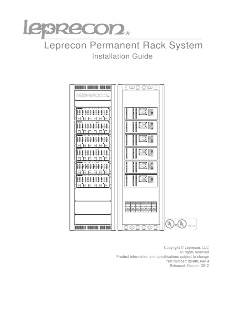
Leprecon Permanent Rack System
Installation Guide
LISTED
Copyright © Leprecon, LLC
All rights reserved
Product information and specifications subject to change
Part Number: 28-0800 Rev G
Released: October 2012
This guide contains the recommended procedures for efficient and safe installation of Leprecon
Permanent Rack systems. Available base model numbers are show below.
•
•
•
•
LPR-24-12; LPR-24-24; LPR-24-36, LPR-24-48
LPR-37-12; LPR-37-24; LPR-37-36; LPR-37-48; LPR-37-60; LPR-37-72
LPR-40-12; LPR-40-24; LPR-40-36; LPR-40-48; LPR-40-60; LPR-40-72; LPR-40-84
LPR-44-12; LPR-44-24; LPR-44-36; LPR-44-48; LPR-44-60; LPR-44-72; LPR-44-84;
LPR-44-96
L
Leprecon
Dimming
System
P
R
24
48
2K
1K = 10A CH
2K = 20A CH
#Channels
Enclosure size in Rack Units
In the example above, the base system consists of a 24RU enclosure with four 12 channel, 20A
per channel Leprecon dimmers.
Dimming systems may be fitted with 10 amp or 20 amp model dimmers, or a combination of
both. Wiring requirements are stated for 20 amp systems, if 10 amp dimmers are used, the
power requirements obviously half of the stated requirement.
Warning - This information is provided for the use of qualified personnel only.
1) General Information
Leprecon dimming systems are fully assembled and tested before shipment. When the
dimming system arrives:
•
Check for visible signs of damage to enclosure. Immediately report any damage
to your shipper.
•
Inspect the configuration and confirm that it matches your order. If a discrepancy
is discovered, contact the Leprecon Service Department at (888) 422-3537. Our
normal business hours are 8:30 a.m. to 5:00 p.m. EST Monday through Friday.
2) System requirements
a) Proper Overcurrent Protection
Dimming systems are required by National Electrical Code to be supplied by a
properly sized breaker.
There are instances were the rack can be supplied by a breaker and wiring with
capacity that is less than the full load capacity of the dimming system. For details on
overcurrent protection requirements see NEC section 520.27.
b) Supply and Load Wire Type
Use copper conductors only for wiring Leprecon Dimming Systems. UL requires the
use of 90 degree rated conductors with the ampacity calculated using 75 degree
tables. Section 4 of this manual will provide the fully loaded power requirements for
your Leprecon system. NEC and local codes must be consulted to determine correct
conductor sizes for each system.
c) Clearance and Airflow
Leprecon Dimming Systems are rated for operation with an ambient temperature of
40 degrees Celsius (104 degrees F) or less. Internal fans allow full load operation as
long as this ambient temperature is not exceeded.
Sufficient clearance must be provided to access and fully open the dimming cabinet
front and back doors for service. Doors are 19” wide, and can be easily removed for
easier installation.
d) Cooling requirements
When planning for HVAC load, the following information can be used. Each 20 amp
VX or MX 12 channel pack will generate approximately 2448 BTU per hour when
fully loaded and operated at 100% output.
e) UL Listing
Leprecon installation dimmer systems are UL Listed. The UL File number for this
product is File E112295
3) Rack Placement
The following diagram shows the ‘footprint’ of a typical Leprecon Dimming system.
Field wiring terminals are located as shown. Corner holes dimensioned as 0.530 are
available for bolting down the rack system.
4) Connecting Rack Power
a) Derating of 96 Channel Systems
Rack systems containing 96 circuits of 20 amp dimmers MUST be derated to a lower
total load capacity. The total allowed load for these systems is 218,880 watts. This is
95% of the theoretical capacity of 230,400 watts if the system were not derated.
b) Ampacity and Conductor sizing
This chart shows the proper conductor size to allow 20 amp Leprecon Dimming System
to be used to it’s full load capacity. Note that systems above 48 channels MUST be
wired with three phase service. Wire sizes are based on NEC 310. Further derating may
be necessary based on conditions and local codes.
Note: Conductors must be rated for 90 degrees Celsius.
For fully loaded 20 amp systems. Wire size based on 4 conductors in conduit.
# of
Channels
Single Phase
Current Rating
(A) per leg
Min Wire
Size
# of
conductors
per terminal
12
24
36
48
60
72
84
96
120
240
360
480
N/A
N/A
N/A
N/A
1/0
1/0
4/0
350 MCM
1
2
2
2
Three Phase
Current
Rating (A)
per leg
80
160
240
320
400
480
560
608*
Min Wire
Size
phase and
neutral
3 awg
1/0
1/0
3/0
250 MCM
350 MCM
500 MCM
500 MCM*
# of
conductors
per terminal
1
2
2
2
2
2
2
2
For fully loaded 10 amp systems. Wire size based on 4 conductors in conduit.
# of
Channels
Single Phase
Current Rating
(A) per leg
Min Wire
Size
# of
conductors
per terminal
12
24
36
48
60
72
84
96
60
120
180
240
300
360
420
480
4 awg
1/0
1/0
1/0
3/0
4/0
300 MCM
400 MCM
1
1
2
2
2
2
2
2
Three Phase
Current
Rating (A)
per leg
40
80
120
160
200
240
280
320
Min Wire
Size
phase and
neutral
6 awg
3 ga
1/0
3/0
1/0
1/0
2/0
3/0
# of
conductors
per terminal
1
1
1
1
2
2
2
2
c) Terminal Block Connections
The following drawing shows the layout of the power input terminal blocks used for field
wiring the Leprecon system:
In the case of a single phase system, the Z phase block is eliminated.
If extra height is required, a riser is available from Leprecon that adds approximately 12
inches.
d) Torque specifications
Mains terminal blocks for Leprecon Dimming systems must be properly torqued.
The block screws are tightened with a 7/16” hex wrench. Manufacturer’s
recommended torque specification is 500 in-lbs, and the blocks are rated for use
with wire sizes from #4 to 500 MCM.
5) Load wiring
Each individual 12 channel dimmer pack has field wiring terminals for connecting load
circuits. Terminal strips are provided for hot, neutral, and ground connection to each pack,
and marked accordingly. Terminals have a torque specification of 9 in-lbs.
Hot and neutral connections for each load circuit must connect to the same dimmer pack.
Each hot circuit must have it’s own neutral return. Shared neutral conductors are not
allowed by NEC when used for dimmed circuits, due to possible harmonic currents that
could overload the shared neutral conductor.
This illustration shows the arrangement of terminal strips on the back of each dimmer
module. An insulating cover is provided for each terminal strip.
6) Control wiring
Leprecon systems are provided with industry standard DMX control inputs. Control
input connectors are XLR 5 pin types as specified by USITT.
Your Leprecon dimmer rack will have a male 5 pin XLR connector for data input,
and a female pass-through connector for dasiy-chain connection to other DMX
devices.
Data connections are consistent with the USITT specification:
Pin
Function
1
Data common
2
Data minus
3
Data plus
4
Reserved
5
Reserved


