IBEKO Power AB
- Application Note True Three-phase Test Advantages
1. Introduction
By generating and applying true three-phase test voltage it is possible to test each type of
transformer, wherever it is not possible to test with a single-phase test voltage. Those are
transformers with irregular vector groups like: phase shifting, rectifier, arc-furnace and
traction transformers.
True three-phase test is a very powerful tool for testing turns ratio, phase angle and
excitation current of various kinds of transformers. True three-phase test has many important
advantages compared to the single-phase test.
This application note describes these advantages and gives short description of phase
shifting transformers.
The measurements recorded with true three-phase supply give better insight to the real
operating condition of a transformer.
Main true three-phase test advantages are important for the following tests:
1. Turns ratio,
2. Excitation current,
3. Phase angle.
1. Turns ratio test
The turns ratio of a transformer is defined as the number of turns on its secondary side
divided by the number of turns on its primary side. The ratio of the physical turns on any two
windings could be established simply by measuring the RMS output voltage on one winding,
while applying a known RMS input voltage (of an appropriate frequency) to the other winding.
NOTE:
In a wye (Y) connected system, the line-voltage (phase to phase) is higher than the phase
voltage (phase to neutral) by a factor of the square root of 3 (1.732). In a wye-connected
system, phase-current and line-current are the same.
In the delta ( ) connection, the line-voltage is applied across each phase. The line-current of
a delta connection is higher than the current through the each winding phase (phase-current)
by a factor of the square root of 3 (1.732).
1.1.
Single-phase test voltage
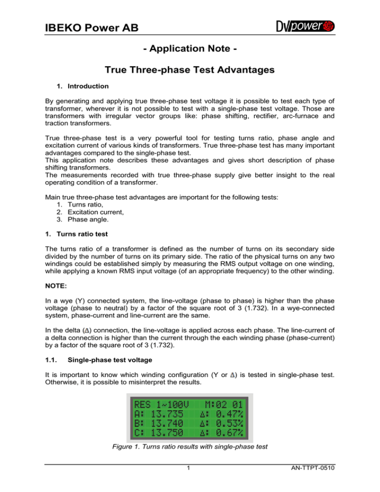
It is important to know which winding configuration (Y or
Otherwise, it is possible to misinterpret the results.
) is tested in single-phase test.
Figure 1. Turns ratio results with single-phase test
1
AN-TTPT-0510
IBEKO Power AB
1.2.
True three-phase test voltage
True three-phase test is very efficient for turns ratio measurement of transformer.
Measurement and comparison of true phase to phase voltage values of primary and
secondary side of the transformer is a great advantage of this test.
Figure 2. Turns ratio results with true three-phase test
Figure 1 and Figure 2 show results of the same measurement during single-phase test
(Figure 1) and during true three-phase test (Figure 2). It can be seen that the results are not
identical. Results of the true three-phase test are credible, because the real phase to phase
voltage values of the primary and secondary side were measured.
Depending on winding configuration, in case of single-phase test, results must be divided or
multiplied by a factor of the square root of 3 (1.732) in order to get the real turns ratio value.
2. Excitation current test
Excitation current can be measured accurately with modern test instruments. Higher than
normal excitation current values may indicate shorted turns or core problems.
2.1.
Single-phase test voltage
The results of single phase excitation current test are shown in Figure 3.
Figure 3. Excitation current results with single-phase test
User must be aware of the transformer winding configuration when analyzing the excitation
current test results in order to calculate line-current value.
2.2.
True three-phase test voltage
The TRT devices with true three-phase testing feature generate a true three-phase excitation
test voltage at three transformer primary windings. The induced three-phase voltages across
the unloaded transformer windings are measured and the transformer turns ratio is
calculated.
One advantage of excitation current measurement with true three-phase test is the ability to
measure line-currents. User does not need to know winding configuration of a transformer
under test in order to obtain the real current value. This greatly helps with testing and
reduces time spent testing and analyzing results.
2
AN-TTPT-0510
IBEKO Power AB
True three-phase test results are shown in Figure 4.
Figure 4. Excitation current results with true three-phase test
Excitation current results with true three-phase test represent real line-current values for any
winding configuration of transformer.
3. Phase angle test
3.1.
Single-phase test voltage
Phase angle is calculated between the same phase on a primary and secondary side. Phase
angle represent the difference between voltage phase angles of primary and secondary side.
Ideally, phase angle should be zero degrees. Offsets significantly greater can indicate fault of
transformer windings. Note that this method of phase angle measurement cannot be applied
when testing phase shifting transformers.
If the angle measured is 180 degrees, it indicates inverse polarity connection.
3.2.
True three-phase test voltage
Another excellent feature of these devices is the ability to measure phase deviation of the
transformer primary versus secondary. This will indicate problems in a transformer such as
partial shorted turns and core faults. This measurement is also useful in verifying phase
errors.
This test is the only test that can verify the operating performance of phase shifting
transformers, and carries an immense importance.
4. Phase shifting transformer
During the last years, importance of phase-shifting transformers, which are used to control
the power flow through transmission lines in meshed networks, has been increasing.
Figure 5. Scheme and basic operating principle of phase shifting transformer
3
AN-TTPT-0510
IBEKO Power AB
These transformers create a phase angle between the primary side voltage and the
secondary side voltage. The purpose of this phase difference is usually to control the power
flow over transmission lines. Both the magnitude and the direction of the power flow can be
controlled by varying the phase angle between the ends of the line.
Figure 6 shows an example of connecting TRT to a phase shifting transformer.
Figure 6. Example of connecting TRT to a phase shifting transformer
2011 IBEKO Power AB, Sweden. All rights reserved.
4
AN-TTPT-0510


