GEA-11315 AKR-30S AKRU
advertisement

GEA-11315
•
Introduction
AKR-305/ AKRU-305
Low Voltage Power
Circuit Breakers
800 Ampere Frame
Table 1 AKR·30S Ratings
The AKR·30S is a new low-voltage ac power circuit breaker
designed to be competitive in size, weight and ratings. It is
provided with the MlcroVersal;rlp® solid-state trip device
currently used on all other AKA low voltage power circuit
breakers.
·
Product Features
The closing mechanism for the AKR-30S low voltage power .
circuit breaker may be eltrier the manually or electrically
. .- .Qperated type. For manual operation, one handle stroke
fl.Y '· '\arges the spring to a predetermined over-center point for
~~ •.~)Ising. For electrical operation, a solenoid charges the
·· · spring to a predetermined over-cen~e.r point for closing.
With both manual and electrical operations, the spring
closing force Is entirely independent o.f the charging
method. The energy stored In the spring provides fast,
uniform energy to close the contacts.
An optional, triple selective trip feature, available with the
AKR-30S, provides both longjime and short time selectivity
up to the short time rating of the breaker, as well as instantaneous system protection between the short time and
short circuit inferruptlng ratings.
Maintainability Is a key feature of the AKR-308. It is
designed with fewer, easier-accessible parts. Combined
with a llghter, 70-pound weight, this means lower cost and
faster maintenance.
System Nominal
Voltage
60 Hz ac
Short Circuit Rating
RMS Symmetrical, KA
with Instantaneous
or Triple Selective
Trip Device
600(635)(1)
480(508)(1)
240(254)(1)
Un fused
22
30
42
Short-Time
Rating
RMS
Symmetrical
KA
Fused
200(2)
200(2)
200(2)
22
22
22
(1) Parenthetical value Is maximum system voltage,
(2) 600 VAC maximum (corresponds to Class J and Class L
fuse maximum voltage rating).
Fuse Sizes: AKRU-308 Integrally Fused - 225-600A Class J,
601·1600A Class L.
Table 2 Breaker Weights · AKR·60·30S,
AKRU·6D·30S
Net Weight (lbs.)
Shipping Weight (lbs.)
Draw Out
Breaker
Element
Manual
Electrical
Manual
Electrical
AKR-308
AKRU-308
70
90
90
110
80
100
100
120
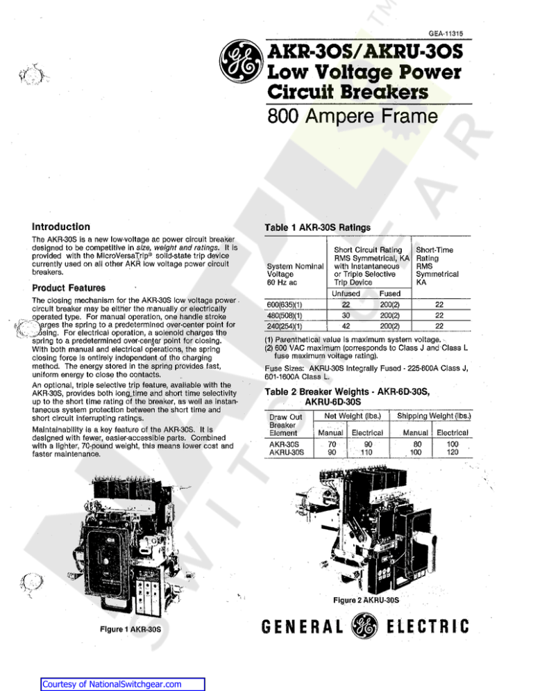
Figure 2 AKRU·30S
Figure 1 AKR·.30$
Courtesy of NationalSwitchgear.com
GENERAL
fj
ELECTRIC
Table 3 MicroVersaTrip® Characteristics for AKR/AKRU·30S
Current
Setting
(Multiple
of Sensor
Current
Rating) (X)
Sensor Current Rating
Tapped
Fixed
Sensors
Sensors
(X) (3)
(X)
100, 150
225, 300
400, 600
800
Adjustable
Instantaneous
Pick-up
(Multiple of
Sensor
Current
Rating) (X)
1.5, 2, 2.5,
3, 4, 6, 8,
10
100, 150
225, 300
or
300, 400
600,800
.5, .6, .7,
.8; .85, .9,.
.95, 1.0
Triple
Selective
Trip with
Fixed
High Range
Instantaneous (3)
(4)
22KA
Fixed
Instantaneous
Override
(Multiple
of Sensor
Amp. Rating
or Tap
Setting) (X)
15
+O
-20%
Long-Time
Short-Time
Pick-up
(Multiple
of Current
Setting) (C)
Delay
(1)
(Seconds)
.8, .9, 1.0,
1.0, 1.1
2.5, 5,
10, 21
Pick-up
(Mu It Ipie
of Current
Setting (C)
Delay
(2)
(Seconds
1.5, 2, 2.5,
3,4,5, 7
9
0.10,
0.22,
0.36
Ground Fault
Short-Time
l2T (1)
(Seconds)
0.4
Pick-up
(Multiple
of Sensor
Current
Rating)
(X)
Delay
(2)
(Seconds)
0.10,
0.22,
0.36
.2, .25.
.3, .35,
.4, .45,
Adjustable
High Range
Instantaneous
(Multiples of
Frame Max.
Short-Time
Rating) (3)
.4, .6, .8
and 1.0
.5, .6
"
(1) Time delay shown at 600% of ampere setting at lower limit of each band.
(2) Time delay shown at Iowa~ limit of each band. All pick-up tolerances are ± 10%.
(3) The only tapped sensors available with high range instantaneous or short time only (triple selective trip) are 200/400, 300/600 or
400/800.
.
(4) Triple selective trip is standard when long time/short time only is required.
Table 4 Repetitive Duty and Normal Maintenance
r;; •
AKR~30S
Circuit
Breaker
Frame
Size
(Amperes)
800
(1)
(2)
(3)
(4)
(5)
(6)
(7)
(8)
(9)
(10)
Number of
Operations
Between
Servicing
1750
Number of
Operations
Rated
Continuous
Current
Switching
(1) (3) (4)
(5) (6) (7)
(8) and (10)
2800
,,,
NumbGr of
No-Load
Operations
Closing and
Opening
(1) (2) (3)
(4) (5) (6)
and (7)
9700
Number of
Operations
Inrush
Current
Switching
(3) (4) (5) (6)
(7) (9) (10)
1400
Servicing consists of adjusting, cleaning, lubricating, tightening, etc., as recommended. When current Is interrupted,
dressing of contacts may be required as well. The operations listed are on the basis of servicing at intervals of 6 months
or less.
When closing and opening no-load.
With rated control voltage applied.
Frequency of operation not to exceed 20 In 10 minutes or 30 in an hour. Rectifiers or other auxiliary devices may further
limit the frequency of operation.
Servicing at no greater intervals than shown in Column 2 above.
No functional parts should have been replaced during the listed operations.
Tile circuit breaker should be in a condition to carry Its rated continuous current at rated maximum voltage and perform at
least one opening operation at rated short-circuit current. After completion of this series of operations, functional part
replacement and general servicing may be necessary.
When closing and opening current up to the continuous current rating of the circuit breaker at voltages up to the rated
maximum voltage and at 85% power factor or higher.
When closing currants up to 600% and opening currents up to 100% of the continuous current rating of the circuit
{ .. ,)}
breaker, at voltages up to the rated maximum voltage, at 80% power factor or higher.
When closing cu'rrents up to 600% of the continuous current rating of the circuit breaker, at voltages up to rated ma\.:.·;;1,;
Imum voltage, at 50% power factor or less, the number of operations shown shall be reduced to 10% of the number listed. ;
If a fault operation ooours before the completion of the listed operations, servicing is recommended and possible functional part replacements may be necessary, depending on previous accumulated duty, fault magnitude; and expected
future operations.
© 1984 GENERAL ELECTRIC COMPANY
Courtesy of NationalSwitchgear.com
Table 7 Undervoltage Device Current
(?'\ccessories
.,)
•
•
•
Shunt Trip
Undervoltage Tripping Device
Auxiliary Switch
Bell Alarm Device (with or without lockout)
Rated Voltage
AG
DC
Operating time (cycles on 60 Hz base)· Closing electrically
(time from energizing closing circuit until contacts touch Is
five cycles.)
Inrush
Sealed
120
.66
.24
240
.37
.12
125
.08
.08
250
.04
.04
Table 5 Closing Mechanism Operating Current
Rated Voltage
120 Volt, 60 Hz
(Operating range
104·127 VAC)
125 Volt DC
(Operating range
100-140 VAC)
Inrush
Sustained
78
153
Recommended
Fuse Size
30
Table 8 Bell Alarm Contact Ratings
Contact
Voltage
AC
44
44
10
240 Volt, 60 Hz
(Operating range
208-254 VAC)
68'
28
15
250 Volt DC
(Operating range
200-280V DC
24
24
6
DC
·'
Contact Rati
Amperes
Inrush
Continuous
10
120
30
240
15
5
480
7
3
125
2.5
2.5
250
0.9
0.9
Table 9 Auxiliary Switch Contact Ratings
'(::''.")
· ·"': C:::::Operating time (cycles on 60 Hz base) · Opening (maximum
clearing time) with Instantaneous 'Overcurrent trip Is three
cycles, and with shunt trip is three and one-half cycles.
Control
Voltage
AC
Table 6 Shunt Trip Current
Voltage
Range
Amperes
Inrush/Sustained
120
104-127
240
208-254
12.3/10.8
3.9/3.4
125
70-140
1.911.9
250
140-280
1.0/1.0
Rated
Voltage
AC
DC
Courtesy of NationalSwitchgear.com
DC
Auxiliary Switch Interrupting
Ratings (Amperes) (1)
Inductive
Non Inductive
115
75
50
240
50
25
480
25
12
48
25
-
125
11
6.3
250
2
1.8
(1) Limit~d to 20A continuous rating of switch on .all breakers
and to 15A continuous rating of #16 wire on draw out
breakers.


