1 INSTRUCTION MANUAL for Tripod Tower Sensor Mounting
advertisement

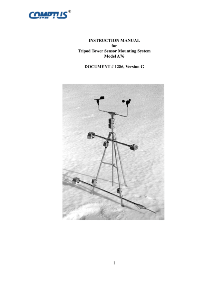
® INSTRUCTION MANUAL for Tripod Tower Sensor Mounting System Model A76 DOCUMENT # 1286, Version G 1 Description Sensor Exposure The Tripod Tower and cross arm assemblies are fabricated from galvanized steel tubing. The Tripod Tower has adjustable mounting feet that allow it to be mounted on a flat surface such as a concrete pad or a pitched surface such as a roof top. It is provided with a mast for attaching wind sensors at a height of 10 feet or 3 meters. Wind Speed Mounting height: Top of mast Wind Direction Mounting height: Top of mast Air Temperature Mounting height: Exposure: 4 - 5 feet (1 - 2 M) North Relative Humidity Mounting height: Exposure: 4 - 5 feet (1 - 2 M) North Orientation The A76 Tripod tower should be oriented with one side of the base parallel to the True North / South Line. This will allow sensors attached to cross arms to be provided a North or South exposure as required. Fuel Temperature Mounting height: Exposure: 10 - 12 inches (25 - 30 cm) South Insolation Mounting height: Exposure: 4 - 5 feet ( 1 - 2 M) South Soil Temperature Mounting Depth: Soil Moisture Mounting Depth: 4 - 20 inches (10 - 50 cm) 4 - 20 inches (10 - 50 cm) Note: Locate soil moisture sensors at least 10 feet (3 meters) from any metallic object such as tower leg or ground rod. 2 ® Figure 1 Tower Orientation 3 ® Figure 2 Tripod Mounting Dimensions Figure 3 Cross Arm Clamp Detail 4 ® Grounding Mounting A ground rod should be installed as close to the tower as possible. It should be electrically connected to the mast and tower legs with a length of wire with as straight a run as possible. The Tripod Tower can be attached to a wooden roof using the screws provided. All penetrations of the roof membrane must be sealed after installation. ESTABLISHING EARTH GROUND If the tower is to be deployed at a remote site, a concrete foundation 3 feet square ( 1 meter square) and 6 inches deep (6.5 cm) should be provided. Attach the tower using bolts preset in the foundation. The spacing of the tower legs is adjustable + 0.5 inch ( + 1.2 cm). A copper-clad rod should be driven into the ground eight feet or more. Since frozen soil is a poor conductor of electricity, the ground rod should extend three feet below the deepest frost line for your area. If the latter is not feasible because of rock formations or other problems, contact the factory for advice. Mast Insert mast through frame at top of tower into triangular bottom support. The “L” shaped The type of soil influences the ability of the ground rod to dissipate energy. Clay and loam bracket attached to the bottom support is to prevent the mast from slipping down. It should are best; sand or gravel poor. Ground rods should be installed as vertically as possible since be positioned inside the mast tube. surface soil generally has a lower conductivity Tighten six screws supporting the mast. than subsoil. Lightning protectors should be attached to this mast as close to their respective sensors as possible. Buried Cable Close lightning strikes present special problems for systems using buried cable. Energy dissipating from a lightning strike can result in earth potentials of several thousand volts per meter. For cable lengths over 5 meters, the potential voltage difference from one end of the cable to the other can easily exceed the insulation breakdown voltage. This can damage attached circuitry and the cable. Pole Mounted A96 Surge Arrestor To help avoid this problem AWG # 8 or larger bare copper wire should be buried adjacent to the signal cable and attached to earth ground at both ends. Avoid sharp turns and coils in the bare copper wire. The bare copper wire will conduct the majority of the lightning-induced current and keep the components tied to the signal cable at nearly the same potential, thus preventing damage. 5 ® A76-SD Support for Anemometer and Wind Vane A76-X5 Cross Arm This cross arm is intended to support a variety of sensors designed to couple with one inch electromechanical tubing. The A76-X5 Cross Arm should be generally be aligned with the North / South line to provide proper exposure for the sensors. See Figure 1. Attach the cross arm to the tower at a height of 4 - 5 feet ( 1.2 - 1.5 M) using the stainless steel U bolt arrangement shown in Figure 3. The U bolt plates should be located on the inside of the tower leg to make the cross arm as stiff as possible. Use a carpenter’s level or other means to make the cross arm as level as possible. This assembly is designed to support the Model A75-104 Three Cup Anemometer and A75-302 or A75-301 Wind Direction Vane. 1. Attach the anemometer and wind vane to the supporting 0.5 inch tube using the cotter pins. 2. Secure the sensors to the tube with a set screw in their base. 3. Note the orientation of the North arrow of the wind vane. 4. Slip the wind sensor assembly over the supporting mast and align the wind vane to True North. A76-I Pyranometer Mount This mount is designed to provide a mounting base for the LI-200 Pyranometer. 5. Tighten the set screw attaching the wind sensor assembly to the mast in the tripod tower. Install the mounting bracket for the pyranometer on the South facing end of a cross arm with a height of 4 - 5 feet (1.2 - 1.5 M). Adjust the base to be as level as possible and tighten the set screw. Remove three retaining nuts from the retaining screws and slide the pyranometer onto the base. Use the three adjusting legs on the pyranometer base to level the base. Secure the base with the three retaining nuts. 6 ® A76-T Mount A76-HT Mount This mount is intended to support an air temperature sensor on the North facing end of a cross arm or attached to a North facing wall. This mount is intended to support an air temperature and relative humidity sensor on the North facing end of a cross arm. The cross arm should be at a height of 4-5 feet (1.2 - 1.5 M) with a North / South orientation. It is provided with a passive radiation shield for the A70-HT Air Temperature and Humidity Sensor. When used with the A76 Tripod Tower the cross arm should be at a height of 4-5 feet (1.2 - 1.5 M) with a North / South orientation. It is provided with a passive radiation shield for the S93 Air Temperature. The assembly should be oriented so that it is not reached by direct sunlight. The tube protecting the temperature sensor must be mounted on a slope to allow any moisture entering it a free drain path. Tighten the retaining screw. Install the A70-HT Temperature and Humidity sensor in the radiation shield and slide the assembly over the North end of the cross arm. The sensor is protected by the screen cover protruding from the side of the enclosure. The assembly should be oriented so that it is not reached by direct sunlight and is shielded from precipitation. Tighten the retaining screw. When wall mounted fasten the A76-T to a North facing wall such that the tube protecting the temperature is on a slope to allow any moisture entering it a free drain path Figure 4 A76-HT Mount & Radiation Shield A76-T Mount 7 ® LIMITED WARRANTY RIGHTS WHICH VARY FROM STATE TO STATE. SOME STATES DO NOT ALLOW THE EXCLUSION OR LIMITATION OF INCIDENTAL OR CONSEQUENTIAL DAMAGES OR LIMITATIONS ON HOW LONG AN IMPLIED WARRANTY LASTS, SO THE ABOVE LIMITATIONS AND/OR EXCLUSIONS MAY NOT APPLY TO YOU. This warranty complies with the Magnuson-Moss Consumer Warranty Act, and completely replaces any warranty printed on promotional material describing products of Comptus Inc. . COMPTUS Inc. extends this warranty to the original consumer only. Any product manufactured by Comptus is warranted against defect for a period of ONE YEAR beginning on the date of purchase by the consumer or two years beginning on the date of purchase from Comptus by the authorized dealer, whichever expires sooner. TO OBTAIN WARRANTY SERVICE, the purchaser must contact Comptus and receive return authorization. Such correspondence should be addressed to: Comptus Inc., 202 Tamarack Rd., Thornton, NH. 03285. All warranty service is performed at the factory. All incidental expenses, including shipment of products to Comptus by the purchaser, shall be the sole responsibility of the purchaser. WARRANTY SERVICE is at the sole discretion of Comptus and free of charge for parts and labor. Under the above terms, Comptus will repair or replace the defective component(s), provided that: HOW TO RETURN EQUIPMENT TO COMPTUS 1. Contact the Comptus Service department with the model and serial number of the unit. Be prepared to provide the symptoms of the problem as many are solved without the need for returning the equipment. Have a person with firsthand experience of the trouble on hand to provide specific information. 2. Comptus will issue a Return Material Authorization Number (RMA#) if required. This will ensure the fastest response and least cost for all parties. Please reference this number in all correspondence. This number should be printed on the shipping container. a) the product has not been subjected to abuse, neglect, accident, alteration, improper installation or servicing, or used in violation of instructions furnished by Comptus; b) the product has not been repaired or altered by anyone except Comptus or its authorized service agencies; 3. Include a description of the service desired with the returned equipment. If the equipment is being returned for repair, please include a description of the problem. c) the serial number has not been defaced, removed, or otherwise changed; 4. If the equipment is packaged in a plastic case, wrap it in aluminum foil, or other conductive material. This will protect it from static electricity, as well as prevent the packing material from jamming mechanical parts, such as switches. Otherwise, place the equipment in a plastic bag, again to prevent contamination by packing material. d) the damage has not been caused by acts of nature including windstorm and hail beyond those specified as within the range of operating conditions; e) the damage has not been caused by shipping. THIS WARRANTY IS IN PLACE OF ALL OBLIGATIONS OR LIABILITIES ON THE PART OF COMPTUS FOR DAMAGES. IT DOES NOT APPLY TO ANY COMPONENT OR EQUIPMENT RESOLD BY COMPTUS IN ITS ORIGINAL CONDITION AS RECEIVED BY COMPTUS FROM THE MANUFACTURER OR DISTRIBUTOR, AMONG THE DAMAGES EXCLUDED FROM THIS WARRANTY ARE ANY INCIDENTAL OR CONSEQUENTIAL DAMAGES ARISING OUT OF OR IN CONNECTION WITH THE PRODUCT IN ANY WAY. Any implied warranties are limited in duration to the duration of the written warranty. No representative or person is authorized to give any other warranty or assume for Comptus any other liability in connection with the sale of its products. THIS WARRANTY GIVES YOU SPECIFIC LEGAL RIGHTS, AND YOU MAY ALSO HAVE OTHER Place the equipment in a suitable shipping container and fill with packing material. There should be at least one inch of packing material between the equipment and the shipping container on all sides. 5. Equipment will be returned C.O.D. to sender if any charges are incurred, unless other arrangements are made in advance. SHIP THE EQUIPMENT TO: Comptus 202 Tamarack Rd. Thornton NH 03285 U.S.A. Telephone : 603 726-7500 Telfax : 603 726-7502 e-mail : service@comptus.com 8 NOTE: Please be sure to include the RMA Number, as described in Item 1, on the shipping container. ® Packing List A76 Tripod Tower Quantity Description 1 6 1 6 5 foot Tower 5.6" Black Cable Ties 5 Foot Mast Mounting Screws A76-HT Cross Arm 1 1 4 4 Cross Arm Radiation Shield U bolts 5.6" Black Cable Ties A76-I Cross Arm 1 1 4 4 Cross Arm Pyranometer Support U Bolts 5.6" Black Cable Ties A76-SD Wind Sensor Mount 1 6 Sensor Mount 5.6" Black Cable Ties 9 ® ® 10 WWW.COMPTUS.COM Phone: 603 726-7500 Fax: 603 726-7502


