Trident® TRX SERIES
Three-Phase Central Lighting Inverter System, 10 to 30 kVA
Catalog Number
Comments
FEATURES
Type
Application
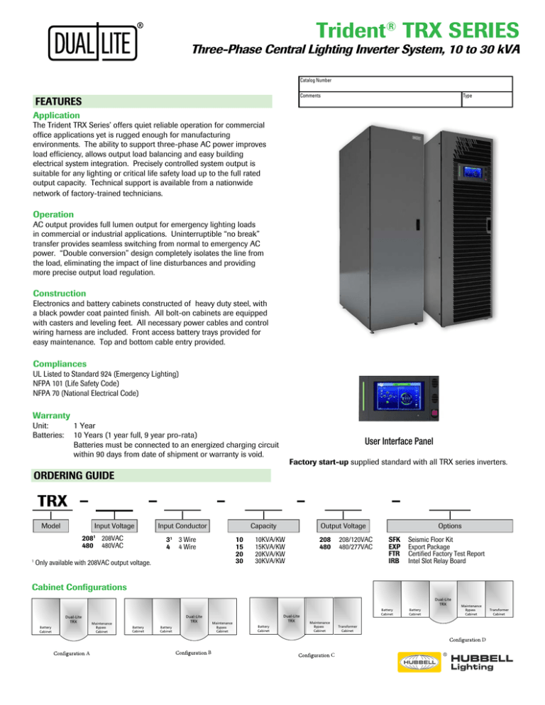
The Trident TRX Series’ offers quiet reliable operation for commercial
office applications yet is rugged enough for manufacturing
environments. The ability to support three-phase AC power improves
load efficiency, allows output load balancing and easy building
electrical system integration. Precisely controlled system output is
suitable for any lighting or critical life safety load up to the full rated
output capacity. Technical support is available from a nationwide
network of factory-trained technicians.
Operation
AC output provides full lumen output for emergency lighting loads
in commercial or industrial applications. Uninterruptible “no break”
transfer provides seamless switching from normal to emergency AC
power. “Double conversion” design completely isolates the line from
the load, eliminating the impact of line disturbances and providing
more precise output load regulation.
Construction
Electronics and battery cabinets constructed of heavy duty steel, with
a black powder coat painted finish. All bolt-on cabinets are equipped
with casters and leveling feet. All necessary power cables and control
wiring harness are included. Front access battery trays provided for
easy maintenance. Top and bottom cable entry provided.
Compliances
Dual-Lite
TRX
UL Listed to Standard 924 (Emergency Lighting)
NFPA 101 (Life Safety Code)
NFPA 70 (National Electrical Code)
Maintenance
Bypass
Cabinet
Battery
Cabinet
A
Warranty
Unit:
Batteries:
1 Year
10 Years (1 year full, 9 year pro-rata)
Batteries must be connected to an energized charging circuit within 90 days from date of shipment or warranty is void.
ORDERING GUIDE
User Interface Panel
Battery
Cabinet
Maintenance
Bypass
Cabinet
Dual-Lite
Factory
start-up supplied standard with all TRX series inverters.
TRX
Maintenance
Bypass
Cabinet
Battery
Cabinet
B
TRX
A
Input Voltage
Model
2081 208VAC
480 480VAC
1
Dual-Lite
TRX
Battery
Cabinet
Input Conductor
Capacity
Dual-Lite
TRX
3 3 Wire
Battery
4 4 Wire
Cabinet
1
Maintenance
Bypass
Cabinet
Only available with 208VAC output voltage.
A
10
15
20
30
Dual-Lite
TRX
Output Voltage
10KVA/KW
15KVA/KW
Battery
Battery
20KVA/KW
Cabinet
Cabinet
30KVA/KW
208 208/120VAC
480 Maintenance
480/277VAC
Dual-Lite
TRX
Bypass
Cabinet
SFK
EXP
FTR
IRB
Battery
Cabinet
OptionsMaintenance
Bypass
Cabinet
Seismic Floor Kit
Export Package
Certified Factory Test Report
C
Intel Slot Relay Board
B
Cabinet Configurations
Dual-Lite
TRX
Dual-Lite
TRX
Maintenance
Bypass
Cabinet
Battery
Cabinet
Dual-Lite
TRX
Battery
Cabinet
Maintenance
Bypass
Cabinet
Battery
Cabinet
Dual-Lite
TRX
Battery
Cabinet
Battery
Cabinet
Maintenance
Bypass
Cabinet
Battery
Cabinet
Maintenance
Bypass
Cabinet
Transformer
Cabinet
Transformer
Cabinet
D
B
A
Dual-Lite
TRX
Dual-Lite
TRX
Battery
Maintenance
Bypass
Transformer
Cabinet
C
Transformer
Dual-Lite
TRX
Maintenance
Trident® TRX SERIES
Three-Phase Central Lighting Inverter System, 10 to 30 kVA
SPECIFICATIONS
Input
Transient Response Time: Recover to ±5% of output voltage within 1/2 cycle
Voltage: 208 or 480VAC, 3- or 4-Wire
Voltage Range: +20%, -15% of nominal without derating
Voltage Distortion: For linear loads, 2% THD. Less than 5% THD for 100% nonlinear
loads without kVA/kW derating
Frequency Range: 40-70Hz.
Phasing Balance: 120° ±1.0° for balanced load; 120° ±1.5° for 100% unbalanced load
Current Distortion: 5% maximum reflected THD at full load
Frequency Regulation: ±0.1% to ± 0.25%
Current Limit: 115% of nominal AC input current maximum
Load Power Factor Range: 0.50 lagging to 0.90 leading without derating
Power Factor Range: 0.99 lagging minimum at full load
Overload: 110% of full load for 60 minutes; 125% for 10 minutes; 150% for one minute,
with true sinusoidal waveform
Protective Circuitry: Withstands input surges of 4kV (Line to Ground) without damage
as per criteria listed in EN 61000-4-5: 1995
General
Output
Operating Temperature Range:
Voltage: 120/208, 277/480VAC, 3- or 4-Wire
Electrical Cabinet: 0°C to 40°C (32°F to 104°F)
Voltage Adjustment Range: ±5%
Battery Cabinet: 20°C to 30°C (68°F to 86°F)
Voltage Regulation: ±1% for balanced load, ±2% for 100% unbalanced load
Relative Humidity: 0-95% non-condensing
Dynamic Regulation: ±5% deviation for 100% load step; ±1% for loss or return of AC
input
Operating Altitude: Up to 3,300 ft. (1,000m) without derating
Acoustical Noise: Less than 59 dBA typical, measured 55 in. (1.4 m) from the unit
SITE PLANNING DATA
System Rating
Voltage (VAC)
AC input
Battery
AC Output
Current(A)
Mechanical Data
Current (A)
Dimensions
Weight
Heat Dis.
Ordering Number
kVA
kW
Input
Output
Nnm
Max
Rec.
OCPD
Nom.
VDC
Max
Discharge
Nom.
Rec.
OCPD
No. of
Cabinets
Cabinet
Config
W x D x H, in
lb
BTU/HR
TRX-208-4-10-208
10
10
208
208/120
30
34
45
288
47
28
40
3
A
44.1 x 39.4 x 78.7
2400
2217
TRX-480-3-10-208
10
10
480
208/120
13
15
20
288
47
28
40
3
A
59.8 x 39.4 x 78.7
2400
3855
TRX-208-3-10-208
10
10
208
208/120
31
36
45
288
47
28
40
3
A
59.8 x 39.4 x 78.7
2400
2217
TRX-480-4-10-480
10
10
480
480/277
13
15
20
288
47
12
15
4
C
67.7 x 39.4 x 78.7
4119
5493
TRX-208-4-15-208
15
15
208
208/120
45
51
70
288
70
42
60
4
B
56.7 x 39.4 x 78.7
4116
3245
TRX-480-3-15-208
15
15
480
208/120
20
23
30
288
70
42
60
4
B
72.4 x 39.4 x 78.7
4116
5258
3245
TRX-208-3-15-208
15
15
208
208/120
46
53
70
288
70
42
60
4
B
72.4 x 39.4 x 78.7
4116
TRX-480-4-15-480
15
15
480
480/277
20
23
30
288
70
18
25
5
D
80.3 x 39.4 x 78.7
5583
7271
TRX-208-4-20-208
20
20
208
208/120
59
68
90
288
93
56
70
4
B
78.7 x 39.4 x 78.7
5638
3843
TRX-480-3-20-208
20
20
480
208/120
27
31
40
288
93
56
70
4
B
94.5 x 39.4 x 78.7
5638
6576
TRX-208-3-20-208
20
20
208
208/120
62
71
90
288
93
56
70
4
B
94.5 x 39.4 x 78.7
5638
3843
TRX-480-4-20-480
20
20
480
480/277
27
31
40
288
93
24
30
5
D
102.4 x 39.4 x 78.7
6815
9309
TRX-208-4-30-208
30
30
208
208/120
89
102
150
288
140
83
110
4
B
100.8 x 39.4 x 78.7
7330
6189
11137
TRX-480-3-30-208
30
30
480
208/120
40
46
60
288
140
83
110
4
B
116.5 x 39.4 x 78.7
7330
TRX-208-3-30-208
30
30
208
208/120
93
107
150
288
140
83
110
4
B
116.5 x 39.4 x 78.7
7330
6189
TRX-480-4-30-480
30
30
480
480/277
40
46
60
288
140
36
45
5
D
124.4 x 39.4 x 78.7
8773
16085
NOTES FOR SITE PLANNING DATA:
1. Input and bypass cables must be run in separate conduit from output cables
2. Minimum-sized grounding conductors to be per NEC 250-122. Parity-sized ground conductors
are recommended. Neutral conductors to be sized for full capacity per NEC 310-15(B)(4).
References are to NEC 2008.
3. Wiring requirements:
AC Input: 3-phase, 4-wire, plus ground
AC Output: 3-phase, 3- or 4-wire, plus ground
4. All wiring is to be in accordance with national and local electrical codes.
5. Minimum cabinet access clearance: 3 ft. (0.9m) front, 18 in. (457mm) overhead.
6. Top or bottom cable entry through removable access plates. Punch plate to suit conduit size,
then replace.
7. Control wiring and power wiring must be run in separate conduit.
8. Output voltage is from BDC output
9. Dimensions are system dimensions including UPS, bypass, transformer and battery cabinets;
bypass cabinets are front access.
10. Weights are system weights including UPS, bypass, transformer and battery cabinets.
11. Heat dissipation of UPS and transformer cabinets.
12. Recommended AC input external overcurrent protection is based on 80% rated devices and
maximum input current limit settings.
Dual-Lite • www.dual-lite.com
ADDITIONAL NOTES:
• If site configuration includes a backup emergency generator, it is recommended that the
engine generator set be properly sized and equipped for a UPS application. Generator
options would typically include an isochronous governor (generator frequency regulation)
and a UPS compatible regulator (generator voltage regulation). Consult generator
manufacturer for required generator options and sizing.
• If site configuration includes an automatic transfer switch, refer to Power Line titled “Criteria
for Application of Automatic Transfer Switches (ATS) With Uninterruptible Power Supply
(UPS) Systems,” publication 91K-PLT-48-02. It is also recommended that the transfer switch
be equipped with auxiliary contacts for inverter “on generator” current limit. Consult transfer
switch manufacturer for required transfer switch options and sizing.
• If site configuration requires an external isolated maintenance bypass circuit, it should be
noted that utility AC input might not be in phase with the UPS AC output. Consult a Hubbell
Lighting, Inc. sales representative or applications engineer.
A Hubbell Lighting, Inc. brand with representatives’ offices in principal cities throughout North America.
Copyright © Hubbell Lighting, Inc., All Rights Reserved • Specifications subject to change without notice. • Printed in U.S.A. 0601861 09/16


