2
TM
XRM Series
X-Ray / Laser Receptacle Modules
For Use With Bender's Isolated Power Systems
Technical Bulletin
NAE2092171 / 05.2014
XRM Series
X-Ray / laser receptacle module
for healthcare facilities
Introduction
BENDER XRM series x-ray/laser receptacle modules provide a convenient source of power
for portable x-ray and laser equipment. Designed in strict compliance with UL standards,
the XRM modules are a high quality outlet device accessory that is fully compatible with
BENDER isolated power panels.
General
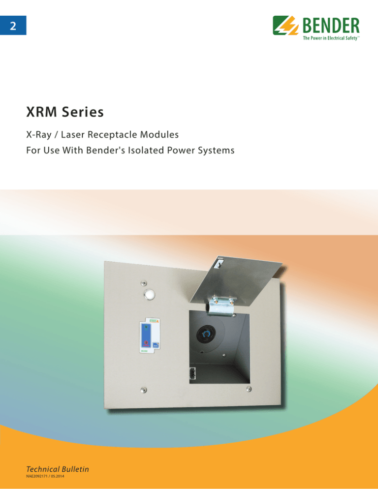
Type XRM modules include power receptacle which matches the NEMA plug configuration of the x-ray or laser equipment. In addition, the module may include a remote alarm
indicator for the connected line isolation monitor at the isolated power panel. The associated isolated power panel will have a programmable logic controller (PLC) that works in
tandem with the module to activate or deactivate the receptacle.
XRM Series
Features
•
Applications: Modules with flush or surface mounted receptacles for use with xray and laser equipment
•
Mounting: Available for flush- or surfacemounted applications
•
Options: Available with door contacts,
"in-use" lamp, and BENDER line isolation
monitor remote indicators
Backbox
For flush mounted applications, the backbox is fabricated from a minimum of 16 GA galvanized steel. Surface mounted enclosures are finished with a coat of hospital ivory baked
enamel or equivalent. The appropriately sized backbox is shipped with the XRM interior
section.
Front Trim
Manufactured from a minimum of 14GA type 304 stainless steel with a #4 brushed finish,
the front trim contains a door with hidden hinges and touch latch that covers the recessed
power receptacle. The front trim for flush mounted XRM modules extends 1" on all sides
beyond the perimeter of the backbox. For surface mounted XRM modules, the front trim
has the same dimensions as the enclosure.
Receptacle
The Type XRM modules can incorporate either an industrial specifiation or hospital grade
receptacle with amperage and voltage as required by the X-Ray/Laser equipment. As an
option, BENDER can provide a user selected receptacle with a matching plug.
Option: "IN USE" Lamp
“IN USE” lights indicate system status for systems with multiple receptacles. The light in the
off state indicates the receptacle can be used. The on state indicates the receptacle cannot
be used. For systems that allow only one receptacle energized at a time, the light will be
off on the XRM in use and illuminated on all other modules indicating the system is at capacity.
For systems that allow more than one receptacle to be energized at a time, the lights will
be off until all allowable receptacles are in use.
LIM Remote Indicators
The MK2000 series remote indicator duplicates the audible and visual alarm indications of
the BENDER LIM2010 line isolation monitor (LIM) installed in the Isolated Power Panel. It is
powered by a 12VDC signal from the LIM. There is a green LED which indicates a "SAFE“
condition, a red LED which indicates a "HAZARD“ condition, and a "MUTE“ switch with inegral amber LED which indicates that the audible alarm has been placed in "MUTE“ mode.
Optionally, a system muting function can be provided which causes the LIM at the panel
location to also be silenced when the "MUTE“ switch is depressed.
The "SAFE“ LED remains ON in the normal mode of operation until the Total Hazard
Current (THC) exceeds the threshold limit of either 5 mA or 2 mA, depending on the
specifications of the connected line isolation monitor. When the alarm condition occurs ,
the "SAFE“ LED goes OFF, the "HAZARD“ LED comes ON, and the audible alarm can be
heard from a distance of at least 25‘ from the unit.
Refer to remote indicators datasheet for more information on available options.
2
Sample outline: XRM module with MK2000 remote indicator and in-use lamp (example part number: XRM-5B2)
14.00"
12.00"
1
4.00"
13
12
4
11
7
BENDER
SAFE
10.00"
HAZARD
8.00"
MUTE
MK2000
8
9
6
10
6
3
1.00"
5
REMOTE INDICATOR
BACK VIEW
SAFE
12V DC COM
HAZARD
1 2345678
PC
BOARD
2
1 Ph RECEPTACLE
(2-Pole, 3-Wire)
TERMINAL BLOCK
11
In-Use (120V)
12
In-Use (0V)
13
14
Door Switch
Door Switch
FRONT VIEW
FROM
ISOLATED POWER PANEL
w/ Control Circuits
TO PANEL
GROUND
REAR VIEW
POWER FROM
RESPECTIVE
CONTACTORS
IN PANEL
1 - Stainless steel faceplate, 14" x 10" (356 x 254 mm)
8 - Green "SAFE" LED indicator
2 - Backbox, galvanized steel, 12" x 8" x 4" (305 x 203 x 102 mm)
9 - Red "HAZARD" LED indicator
3 - Receptacle (example shown: NEMA #6-50R)
10 - Mute pushbutton
4 - Concealed hinge
11 - Terminal block
5 - Hinged door
12 - In-use indicator
6 - Touch latch
13 - Door switch and mounting plate (closed door = open contact)
7 - Remote indicator (example shown: MK2000)
3
Ordering information, step 1: Core components
NOTE: XRM modules are sold in two parts - the front trim assembly and the backbox. Refer to steps 1 and 2 for building the appropriate
part numbers.
XRM -
1 - Receptacle
1: Hubbell #IN16494
2: NEMA #615R
3: NEMA #620R
4: NEMA #630R
5: NEMA #650R
6: NEMA #L615R
7: NEMA #L620R
8: NEMA #L630R
5
B
2
1
2
3
4
2 - Remote Indicator
N: None
A: MK2000P, w/ test button
B: MK2000
C: MK200C, w/ load monitoring
D: MK2000CP, w/ load monitoring and
test button
E: MK2000CBM, w/ digital display
3 - Limit Type
0: None
1: Door Contact (Limit Switch)
2: Door Contact (Limit Switch) and
"In-Use" Lamp
4 - Mounting Type
[ ] (nothing, left blank): Flush Mounting
S: Surface Mounting
Part number
Description
Ordering No.
XRM-1B2
Hubbell IN16494 60A / 250V receptacle, MK2000 series remote indicator,
door switch control with in-use indication
B 5213 01049
XRM-5B2
NEMA 650R, 50A / 250V receptacle, MK2000 series remote indicator,
door switch control with in-use indication
B 5213 01051
XRM-8E2
NEMA L6-30R, 30 A / 250 V receptacle, MK2000CBM series digital remote indicator,
door switch control with in-use indication
B 5213 00168
Part number
Description
Ordering No.
B120804
Backbox, 12" x 8" x 4" (305 x 203 x 102 mm)
B 5213 00367
Ordering information, step 2: Backbox
Your local contact:
TM
USA • Exton, PA • 800-356-4266 / 610-383-9200
Mexico • Tampa, FL • 813-240-2858
info@bender.org • www.bender.org
Canada • Mississauga, ON • 800-243-2438 / 905-602-9990
info@bender-ca.com • www.bender-ca.com
Latin America • Santiago de Chile • +56 2 2933 4211
info@bender-latinamerica.com • www.bender-latinamerica.com
Document NAE2092171 / 05.2014 / © Bender Inc. All Rights Reserved.
Common configurations for step 1

