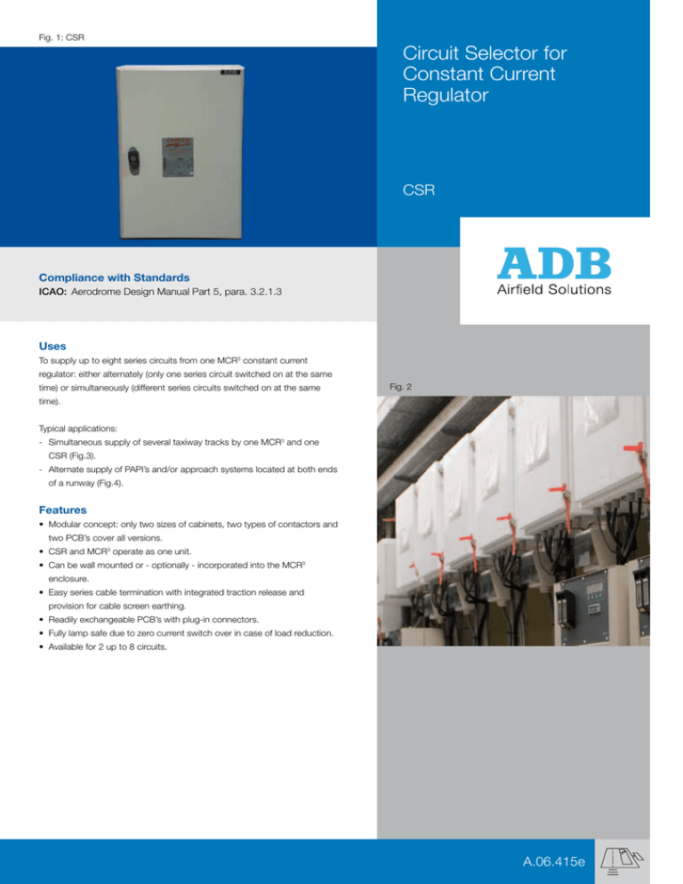
Fig. 1: CSR
Circuit Selector for
Constant Current
Regulator
CSR
Compliance with Standards
ICAO: Aerodrome Design Manual Part 5, para. 3.2.1.3
Uses
To supply up to eight series circuits from one MCR3 constant current
regulator: either alternately (only one series circuit switched on at the same
time) or simultaneously (different series circuits switched on at the same
Fig. 2
time).
Typical applications:
- Simultaneous supply of several taxiway tracks by one MCR3 and one
CSR (Fig.3).
- Alternate supply of PAPI’s and/or approach systems located at both ends
of a runway (Fig.4).
Features
• Modular concept: only two sizes of cabinets, two types of contactors and
two PCB’s cover all versions.
• CSR and MCR3 operate as one unit.
• Can be wall mounted or - optionally - incorporated into the MCR3
enclosure.
• Easy series cable termination with integrated traction release and
provision for cable screen earthing.
• Readily exchangeable PCB’s with plug-in connectors.
• Fully lamp safe due to zero current switch over in case of load reduction.
• Available for 2 up to 8 circuits.
A.06.415e
Concept
Remote or local operation modes are activated by the MCR3.
High-voltage contactor interlock controlled by a microcontroller on
the logic board. The MCR3 switches on after at least one circuit has
Fig. 3
been selected. If no circuit is selected, the MCR3 switches off.
1
Simultaneous operation:
When additional circuits are selected, the current drop is
MCR3
CSR
A-B-C
regulated by the MCR .
3
1-A
1-B
1-C
The output current drops down to zero and rises again to the
selected level in case of de-selection of circuits.
Alternate operation:
Taxiways
The output current drops down to zero and rises again to the
Runway
selected level after another circuit is selected.
Technical Data
Series circuit current: 6.6 A or 20 A.
Max RMS output voltage of series circuit:
- MID range: 1515 V AC (only 6.6 A) (Fig.1)
Fig. 4
- HIGH range: 5000 V AC. (Fig.5)
Auxiliary power supply:
220, 230, 240 or 400V AC (50 or 60 Hz).
Remote control and monitoring via MCR3:
- Multiwire: 24 V or 48 V DC.
- BUS:RS485 standard, point-to-point connection with MCR .
3
2
A-B
C-D
MCR3
CSR
2-C
1-B
Construction
1-A
Cabinet:
2-D
34
Runway
16
Two executions:
1
- MID voltage range: for 6.6 A series circuits up to 1515 V
(up to 10kVA MCR3).
- HIGH voltage range: for 6.6 A and 20 A series circuits up to 5000 V
(up to 30 kVA MCR3).
Finish
Phosphating and baked polyester electrostatic paint coating.
Colour: light grey RAL 7032.
PAPI “16”
PAPI “34”
Standard Options
Remote control and monitoring
The CSR offers the following choices:
Fig. 5
Multiwire remote control with two voltage ranges:
24 or 48 V DC.
This version provides full remote control and back indications;
e.g. selection of circuits, shut-down, remote or local operation, ...
BUS remote control: A microcontroller in the MCR3, using a fieldbus with
hardware according to RS485, allows the remote monitoring of a larger
quantity of parameters (e.g. all dip switch settings).
Hour counters: available via MCR3 HMI
The hour counter of each circuit has following properties:
- Resettable to 0.
- Presettable: an alarm is created when a user-adjustable pre-set time
is reached.
- Output current dependent: the counter starts when a useradjustable
output current level is reached.
Incorporated in MCR3 (on request)
The MID range CSR may be incorporated in the MCR3 enclosure.
(Max. 6.6 A / 1515 V, up to 10 kVA). In this case, a special execution of
the MCR3 has to be ordered.
Dimensions in mm* (Fig.6)
MID range
(600 x 400 x 250)
H
600
800
W
400
600
D
250
300
HL
500
740
WL
450
650
MID range
HIGH range
Weights in kg*
Fig. 6
HL
WL
H
HIGH range
(800 x 600 x 300)
W
Number
of
circuits
Net
Weight
Gross
Weight
Net
Weight
Gross
Weight
2
21
33
50
62
3
23
35
54
66
4
23
35
58
70
5
25
37
62
74
6
25
37
66
78
7
27
39
70
82
8
27
39
74
86
D
* For information only.
Ordering Code
Suggested Specification
CSR M6 S5 3 B C S
Execution
High range 6.6 A = H6
High range 20 A
= H2
Medium range 6.6 A = M6
Number of circuits*
Simultaneous operation
2 circuits = S2
3 circuits = S3
4 circuits = S4
5 circuits = S5
6 circuits = S6
7 circuits = S7
8 circuits = S8
Alternate operation
2 circuits = A2
The circuit selector shall be designed for the alternate supply of two series
circuits or the simultaneous supply of up to eight series circuits from
one constant current regulator.The working voltage and current breaking
capacity shall suit the characteristics of the constant current regulator
associated with the circuit selector. The circuit selector shall be controlled
from the CCR. It shall be provided with electrical interlocks to prevent undue
simultaneous switching of series circuits circuits and to de-energise the
regulator when no series circuit is selected. The switching of series circuits
shall not cause over current in the other series circuits. It shall be possible
to display all status values on an alphanumerical display on the front door of
the circuit selector. The circuit selector shall be housed in a self contained,
metal sheet enclosure, suitable for wall mounting or shall be incorporated in
the constant current regulator. The remote control and monitoring system
shall be available from the CCR as either a 24V or 48V DC multiwire version
or a RS485 hardware BUS version.
Supply voltage (50 or 60 Hz)
220 V - 230 V =3
240 V =4
Remote control
Bus Multiwire 24 V DC Multiwire 48 V DC =B
=2
=4
Hour counter
No = O
Special requirements to be specified in full text = S
* MID range: only even number of circuits.
Complete, delete or modify as necessary.
Registered Office:
Phone: +32 (2) 7221711
Fax: +32 (2) 7221764
info.adb@adb-air.com
www.adb-air.com
© ADB
all rights reserved
order number DOCA06415EV1
subject to modifications
www.comith.be
ADB
Airfield Solutions
Leuvensesteenweg 585
B-1930 Zaventem
Belgium


