ECE 207L - FIRST ORDER RL CIRCUITS
advertisement
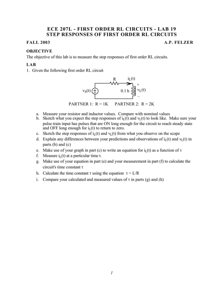
ECE 207L - FIRST ORDER RL CIRCUITS - LAB 19 STEP RESPONSES OF FIRST ORDER RL CIRCUITS FALL 2003 A.P. FELZER OBJECTIVE The objective of this lab is to measure the step responses of first order RL circuits. LAB 1. Given the following first order RL circuit R vs(t) iL(t) 0.1 h PARTNER 1: R = 1K + vL(t) – PARTNER 2: R = 2K a. Measure your resistor and inductor values. Compare with nominal values b. Sketch what you expect the step responses of iL(t) and vL(t) to look like. Make sure your pulse train input has pulses that are ON long enough for the circuit to reach steady state and OFF long enough for iL(t) to return to zero. c. Sketch the step responses of iL(t) and vL(t) from what you observe on the scope d. Explain any differences between your predictions and observations of iL(t) and vL(t) in parts (b) and (c) e. Make use of your graph in part (c) to write an equation for iL(t) as a function of τ f. Measure iL(t) at a particular time t. g. Make use of your equation in part (e) and your measurement in part (f) to calculate the circuit's time constant τ h. Calculate the time constant τ using the equation τ = L/R i. Compare your calculated and measured values of τ in parts (g) and (h) 1
