October 2015
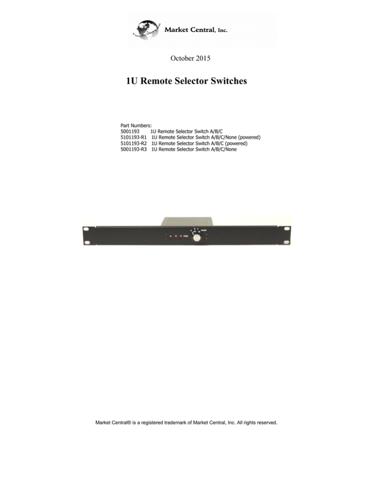
1U Remote Selector Switches
Part Numbers:
5001193
1U Remote Selector Switch A/B/C
5101193-R1 1U Remote Selector Switch A/B/C/None (powered)
5101193-R2 1U Remote Selector Switch A/B/C (powered)
5001193-R3 1U Remote Selector Switch A/B/C/None
Market Central® is a registered trademark of Market Central, Inc. All rights reserved.
1. Specifications
Connectors:
(1) Six position terminal block for dry contact closure outputs. (all models)
(1) 3.5-mm DC power input jack, center positive (powered models only)
(1) Eight position terminal block for remote status dry contact inputs (powered models only)
Indicators:
(1) LED for power, (3) LEDs for remote status indicators (powered models only)
Temperature:
32 to 158ºF (0 to +70ºC) - operating,
14 to 158ºF (-10 to +70ºC) - storage
Relative Humidity: up to 80%, non-condensing
MTBF:
>100,000 hours or 15,000 switching cycles
Power:
100-240VAC, 50/60-Hz wall mount supply, 12VDC output (powered models only)
Size:
5.75”D x 19”W x 1.75”H
Weight:
2 lbs including external wall mount supply
Remote Status Input:
12 VDC supplied thru approximately (powered models only) 240 ohm pullup
resistance to provide wetting current for external dry contacts being monitored.
Resistance of external dry contact and associated cable not to exceed 100 ohms.
Dry Contact Outputs:
50 milliohms typ. contact resistance, 2.5A maximum switching current,
43 W maximum switching power
2. Introduction
The 1U Remote Selector Switch (RSS) devices are general purpose switches with dry contact closure
outputs that can be used to control the selected connection state of other switch devices that have dry
contact closure remote control interfaces. All four models have a front panel rotary switch that allows the
user to close any one of the three rear panel dry contact outputs (A, B, or C connected to G). Two of the
models also allow the user to select NONE of the dry contact closure outputs (all contacts open).
NOTE: When the RSS is used to control the connection state of a SecureSwitch revision B, C or D device,
selecting the NONE position disables the RSS and allows the user to locally control the connection state of
the SecureSwitch device using its front panel pushbutton switches. These selector switch models are
intended to control a single SecureSwitch device. The NONE postion will not work properly if multiple
SecureSwitch devices are connected to the Selector Switch.
The two powered models of the RSS also include status inputs that can be used to monitor the connection
state of other switch devices that have dry contact status output interfaces. These RSS models continuously
display the status of three pairs of external dry contact closure inputs via front panel mounted status LEDs.
When any of the dry contact closure input pairs on the RSS are shorted together, the corresponding front
panel LED on the RSS illuminates. This allows the user to verify that the device being controlled by the
RSS is in the selected connection state.
Note: that the rear panel terminal block connectors on these RSS products have been labeled to match the
SecureSwitch products' Remote Status Output and Remote Control Input connectors to allow easier
installation & operation when used with the SecureSwitch devices. The remainder of this manual describes
using the 1U RSS with these switches.
3. Installation & Operation
All Models:
To control one or more SecureSwitch devices using the 1U Remote Selector Switch, connect the 6 position
terminal block connector on the RSS to the 6 position Remote Control Input terminal block connector on
the SecureSwitch device(s) using a straight through cable (only pins 2, 4, 5 and 6 are used on the 6 position
terminal block). Pin 2 = G, 4 = A, 5 = B & 6 = C
See diagram below.
Fiber Optic
Connections
Rev B
Rev B
Rev B
G A B C
G A B C
G A B C
RSS
A
B
C
G
Connect the 8 position terminal block connector on the powered versions of the RSS to the 8 position
Remote Status Output terminal block connector on the SecureSwitch device(s) (only pins 1, 2, 4, 5, 7 and 8
are used on the 8 position terminal block), using a straight through cable. Pins 1&2 = C status, 4& 5 = B
status or OFF status and 7&8 = A status on the SecureSwitch devices (see the example connection diagram
below).
Note: When in the closed position, the total resistance of each dry contact closure and associated cable that
the RSS is monitoring must be less than 100 ohms in order for the RSS to be able to reliably determine the
contact closure status.
When all of the status and control connections have been made to the RSS, plug the external power supply
into the RSS and then connect the supply to a source of AC power. Installation is now complete and the
unit is ready for operation.
When a powered model of RSS is turned ON, it will illuminate the Power LED indicator on its front panel
and continuously display the state of the SecureSwitch device's status contact outputs that are connected to
the 8 position terminal block inputs on the RSS. For example, if port A is selected on the SecureSwitch, its
A-A status contact outputs will be closed. This will cause the A LED indicator on the RSS to be
illuminated. Likewise, if port B is selected on the SecureSwitch, the B LED indicator will illuminate on the
RSS, and if port C is selected, the C LED indicator will illuminate.
If multiple SecureSwitch devices are connected in parallel to the RSS as shown in the previous diagram,
should any of the SecureSwitch units fail to switch to the selected A, B or C position then multiple LEDs
will be illuminated on the RSS indicating that a fault condition exists.
One consideration when using the above approach is that certain types of faults in the cabling that connect
all of the Remote Status Outputs from the SecureSwitch devices to the RSS could go undetected (open
connections may not be detected). As an alternative, you can connect the A-A pairs of Remote Status
Outputs on each SecureSwitch device in a serial daisy chain (do the same for the B-B and C-C pairs), and
then connect each of these three daisy chains to the appropriate pair of contacts on the 8 position terminal
block on the RSS. With this wiring configuration, the status LEDs on the front of the RSS will only
illuminate if all of the SecureSwitch units have the same port selected. If different ports on two or more
switches are selected for any reason, then none of the A, B or C LEDs on the RSS will be illuminated
indicating that a fault condition exists.
4. Troubleshooting
4.1 Calling Your Supplier
If you determine that your RSS is malfunctioning, do not attempt to alter or repair the unit. It contains no
user-serviceable parts. Contact Market Central, Inc. at
(412) 494-2800
Before you do, make a record of the history of the problem. We will be able to provide more efficient and
accurate assistance if you have a complete description of the problem,
including:
•the nature and duration of the problem.
•when the problem occurs.
•the components involved in the problem.
•any particular applications that, when used, appears to create the problem or make it worse.
4.2 Shipping and Packaging
If you need to transport or ship your 1U RSS:
•Package it carefully. We recommend that you use the original container.
•If you are shipping the switch for repair, make sure you include everything that came in the original
package.
•Before you ship, contact Market Central, Inc. to get a Return Materials Authorization (RMA) number.
MARKET CENTRAL, INC.
WARRANTY AND LIMITATION OF LIABILITY
Market Central, Inc. (“Market Central”) warrants that the products manufactured and sold by it or by one of its authorized
resellers will, when sold, be free of defects in workmanship or material under normal service and use. Products which have been
changed or altered in any manner from their original design, or which are
improperly or defectively installed, serviced or used, are not covered by this warranty. If any failure to conform to this warranty
becomes apparent during a period of one (1) year after date of sale, Market Central shall, upon prompt, written notice and compliance
by the
customer with such instructions as it shall give with respect to the return of defective products or parts, correct such non-conformity
by repair or replacement of the defective part of parts. Correction in the manner provided above shall constitute a complete fulfillment
of all obligations and liabilities of Market Central with respect to the quality of said products. THE FOREGOING WARRANTY IS
EXCLUSIVE AND IN LIEU OF ALL OTHER WARRANTIES OF QUALITY, WHETHER WRITTEN, ORAL OR IMPLIED,
INCLUDING, WITHOUT LIMITATION, ANY WARRANTY OF MERCHANTABILITY OR FITNESS FOR PURPOSE.
THIS WARRANTY AND THE OBLIGATIONS AND LIABILITIES OF MARKET CENTRAL HEREUNDER ARE
EXCLUSIVE AND IN LIEU OF AND BUYER HEREBY WAIVES ALL OTHER REMEDIES, WARRANTIES, GUARANTIES
OR LIABILITIES, EXPRESS OR IMPLIED, ARISING BY LAW OR OTHERWISE (INCLUDING WITHOUT LIMITATION
ANY
OBLIGATIONS OF MARKET CENTRAL WITH RESPECT TO FITNESS FOR PURPOSE, MERCHANTABILITY AND
INDIRECT, SPECIAL OR CONSEQUENTIAL DAMAGES OR LOST PROFITS) OR WHETHER OR NOR OCCASIONED BY
MARKET
CENTRAL’S NEGLIGENCE. THIS WARRANTY SHALL NOT BE EXTENDED, ALTERED OR VARIED EXCEPT BY A
WRITTEN INSTRUMENT SIGNED BY A DULY AUTHORIZED OFFICER OF MARKET CENTRAL.
Market Central Inc.
500 Business Center Drive
Pittsburgh, PA 15205
Phone: (412) 494-2800 www.secureswitch.com
Fax: (412) 494-5550
CAGE Code 1BGJ7
© Copyright 2015 Market Central, Inc. All rights Reserved.

